

Electric Bicycle
- Summary
- Abstract
- Description
- Claims
- Application Information
AI Technical Summary
Benefits of technology
Problems solved by technology
Method used
Image

Examples
first embodiment
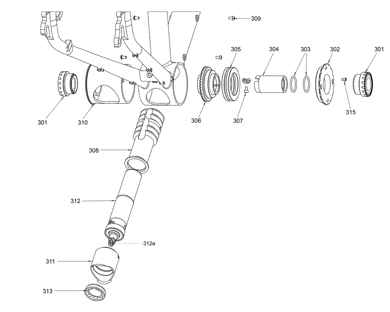
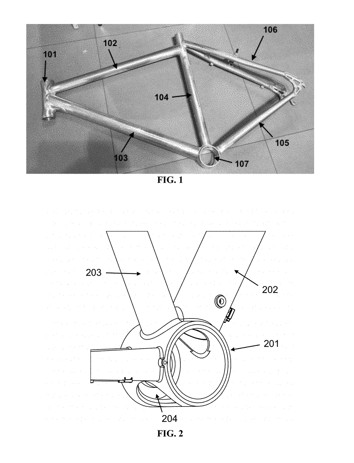
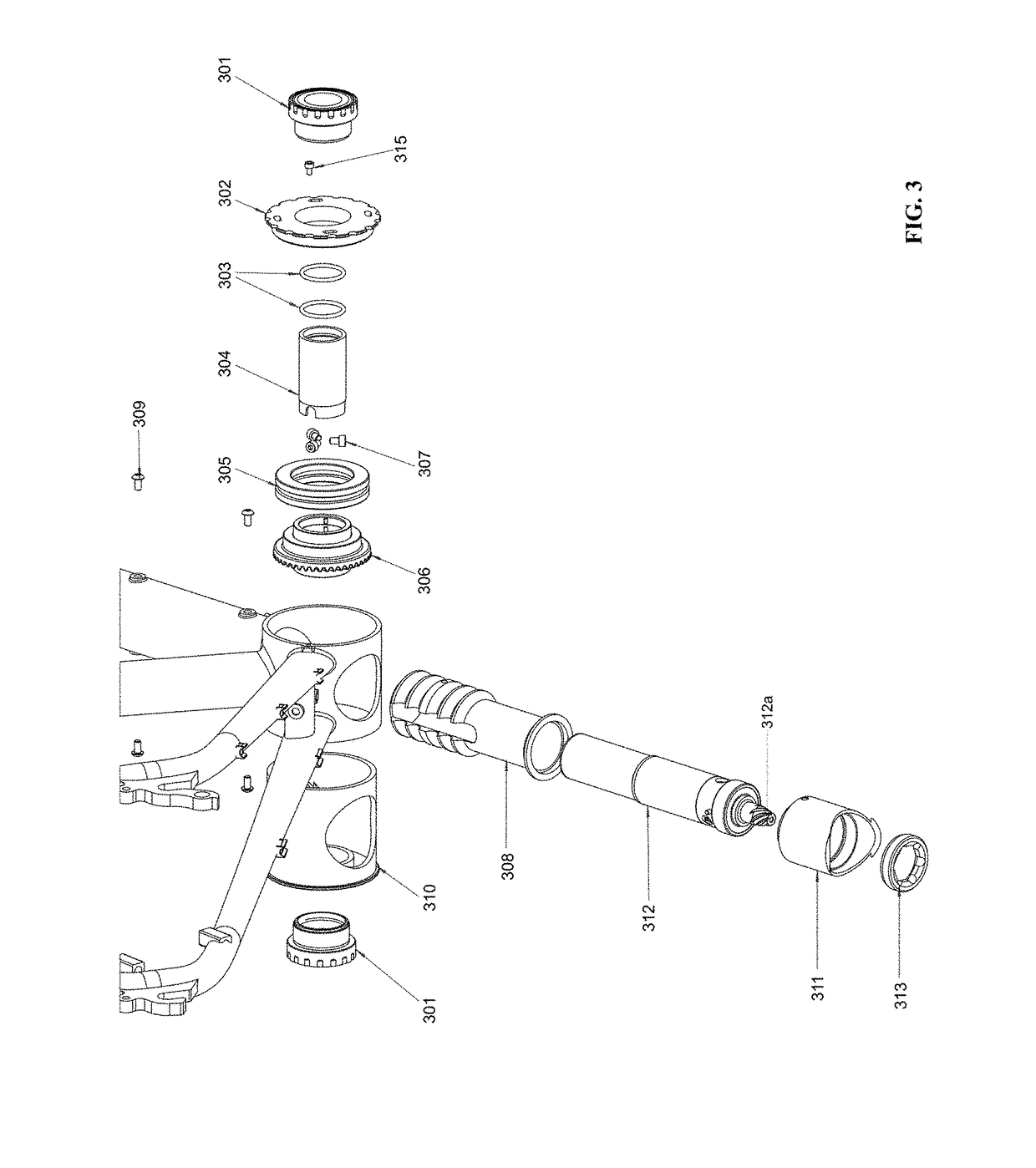
[0024]In the specially designed bicycle frame in accordance to the present invention, the down tube and / or the seat tube are securely connected (e.g. by welding) to the bottom bracket shell on its cylindrical wall. The bottom bracket shell is an open cylinder without its bases covered. The bottom bracket shell provides one or two through-hole(s) at where the down tube and / or the seat tube are connected to the bottom bracket shell. The size(s) of these one or two top through-hole(s) approximately match the sectional width(s) of the down tube and / or the seat tube. This configuration allows the hollow interiors of the bottom bracket shell, the down tube, and / or the seat tube to be interconnected. The bottom-facing side (opposite of the down tube and / or the seat tube) of the cylindrical wall of the bottom bracket shell also has one or more through-hole(s). The openings are axially aligned with the down tube and / or seat tube in their longitudinal directions. These bottom through-hole(s) ...
second embodiment
[0027]In the specially designed bicycle frame, the bottom bracket shell is detachable from the main bicycle frame structure. The down tube and the seat tube are connected to a hub at their bottom ends, or arranged to have their bottom ends fixed at close proximity to each other. In all of the aforesaid configurations, the down tube and / or the seat tube are open at their bottom ends, making the interior space of the down tube and / or the seat tube accessible through their bottom end(s). In the configuration where the down tube and the seat tube are connected to a hub, the hub provides one or two opening(s) at where the down tube and the seat tube join the hub in such a way that access to the hollow interior space of the down tube and / or the seat tube through the hub is unobstructed.
[0028]The detachable bottom bracket shell here is also a cylindrical drum with its the bases uncovered. The bottom bracket shell provides one or two through-hole(s) on its cylindrical wall at location(s) th...
PUM
 Abstract
Description
Claims
Application Information