
Artificial Trachea and Method for Producing the Same

Inactive Publication Date: 2019-05-16
KYOTO UNIV
View PDF0 Cites 0 Cited by
  • Summary
  • Abstract
  • Description
  • Claims
  • Application Information

AI Technical Summary

Benefits of technology

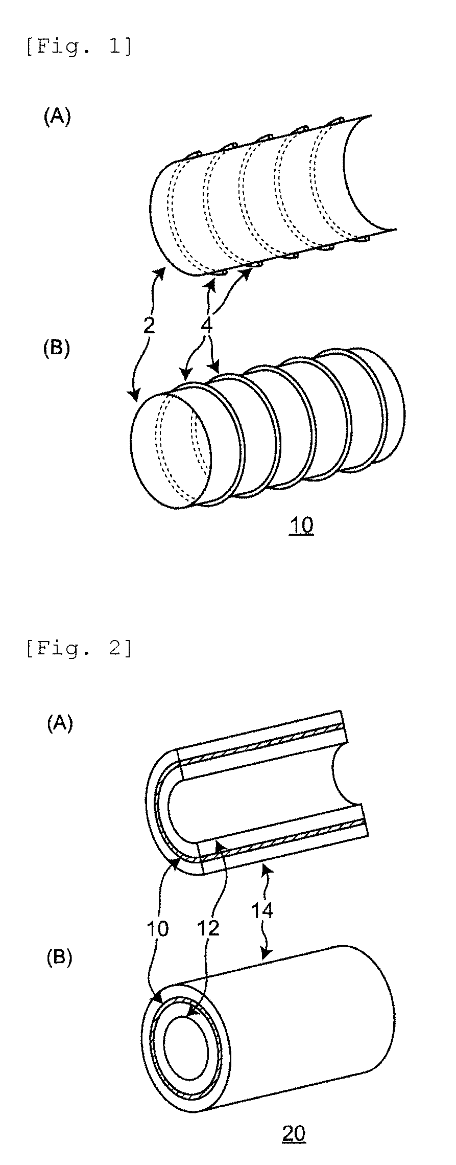
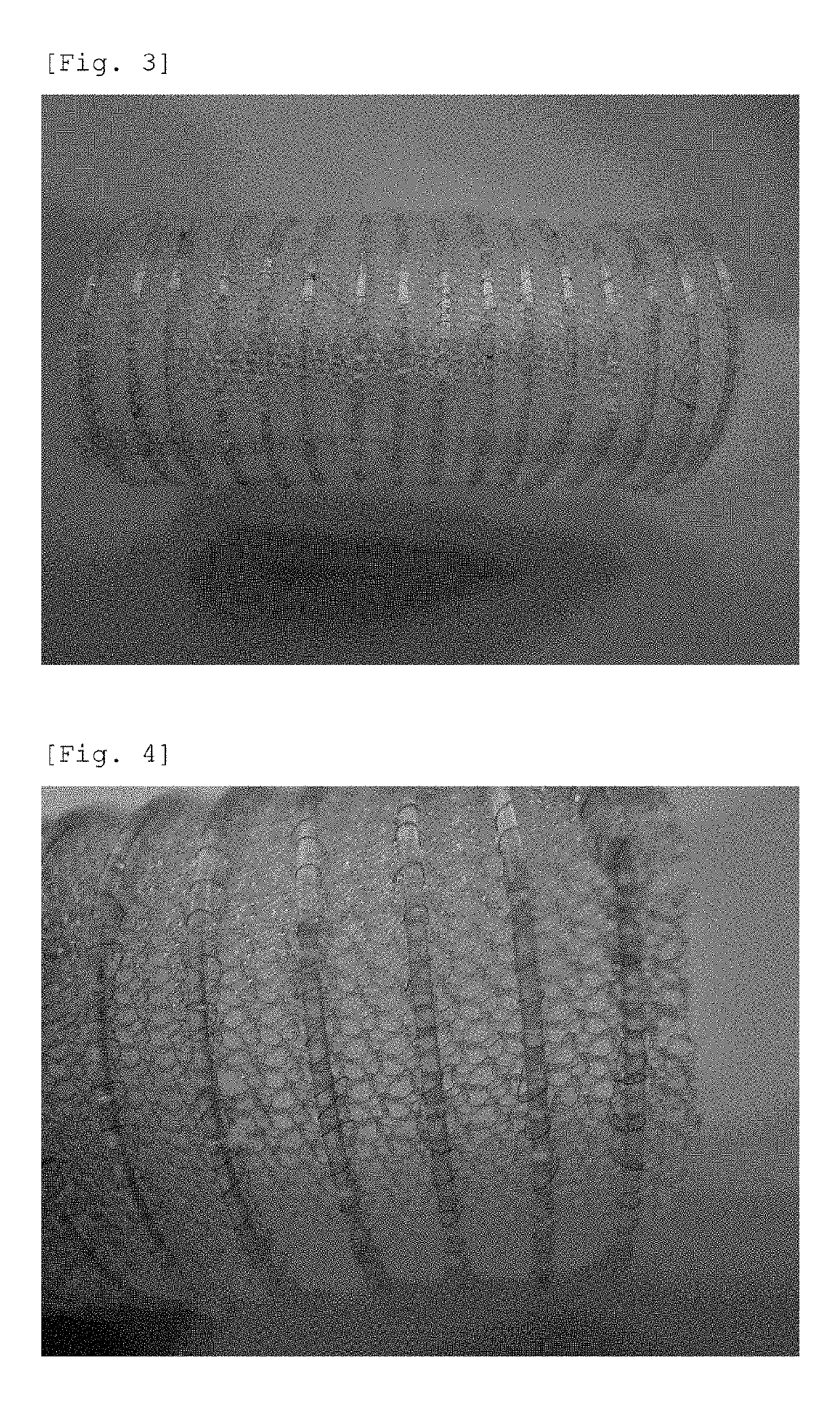
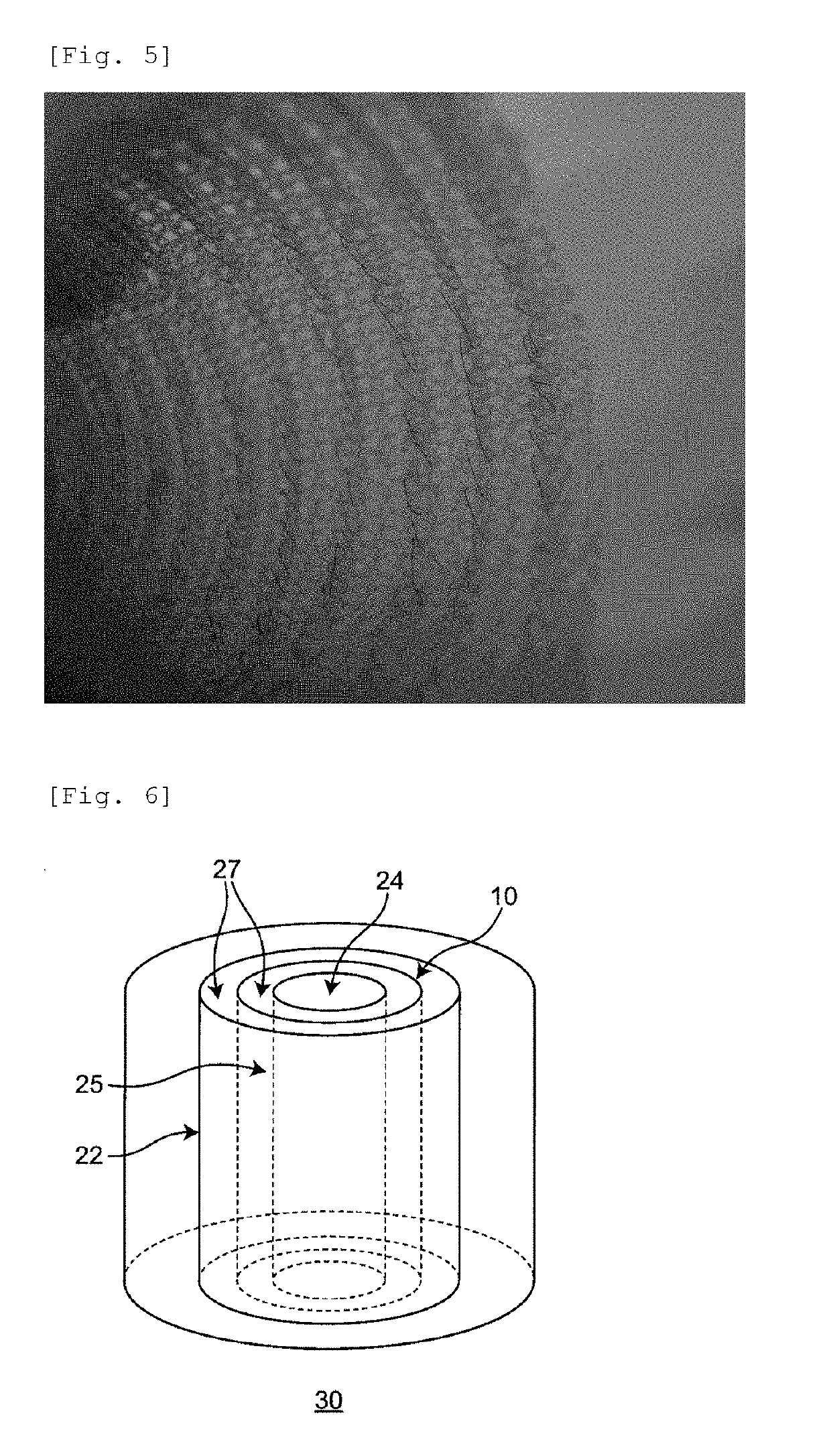
The present invention provides an artificial trachea that has a simple and uncomplicated structure, but is stable over a longer period of time inside a living body and has a mechanical strength capable of retaining the lumen of the artificial trachea over a longer period of time. The artificial trachea has a hollow tubular base material, a plurality of annular support materials placed on the outer periphery of the tubular base material, and porous collagen layers on both the outside and the inside of the tubular base material, all of which are bonded together. The artificial trachea has higher biocompatibility, is more easily incorporated into a living body, and can maintain stable performance over a longer period of time.

Problems solved by technology

Therefore, if this single monofilament is broken, the following problems can arise: the strength of the artificial trachea can totally decrease, and balance of the strength can be deteriorated.
Furthermore, the tubular base material, around the outer periphery of which the support material is wound spirally, may have drawbacks or cause problems as follows: The tubular base material lacks in extensibility in the longitudinal axis direction, and when a twisting force is applied in a spiral direction, the tubular base material is deformed into a collapsed shape, and thus the lumen is likely to be developed in a constriction form.
In JP 6-17715 U, there is also a problem that it is not easy to treat (or deal) an artificial trachea having a complicated form such as a branching form or a form having a non-constant diameter of the trachea.

Method used


Image

  • Artificial Trachea and Method for Producing the Same
  • Artificial Trachea and Method for Producing the Same
  • Artificial Trachea and Method for Producing the Same

Examples


example 1

[0111]A polypropylene mesh (BIRD (registered trademark) mesh: BIRD mesh, manufactured by DAVOL INC.) was formed into a tubular shape to prepare a hollow tubular base material.

[0112]A polypropylene monofilament having a diameter of 0.994 mm (Monofilamente (trade name), manufactured by G. KRAHMER) was wound as a ring (or an annulus) around the tubular base material mentioned above to place an annular support material on the outer periphery of the tubular base material. The contact portion between the annular support material and the tubular base material was fused by melting with heating. Using a 7-0 prolene suture (polypropylene surgical suture Monofilamente (trade name), manufactured by G. KRAHMER), the annular support material was sewn (or fixed) on the tubular base material.

[0113]Similarly, annular support materials were placed on the annular base material at an interval of about 2 to 3 mm to obtain a frame (backbone) of Example 1 which comprised the annular support materials and ...

example 2

[0120]In the same manner as in Example 1, except that a nylon monofilament having a diameter of 1.0 mm manufactured by Toray Industries, Inc. was wound as a ring around the tubular base material mentioned above to place annular support materials on the tubular base material, an artificial trachea of Example 2 was obtained.

example 3

[0121]A BIRD mesh was cut and sewn into a Y-shape to obtain a Y-shaped tubular base material. In the same manner as in Example 1, annular support materials were placed on each of the three Y-shaped branches to obtain a Y-shaped frame of Example 3. A Y-shaped mold was prepared, and collagen layers were placed on the frame of Example 3 using the same method as in Example 1 to obtain an artificial trachea of Example 3.

[0122]FIG. 9 exhibits a photograph of the frame of Example 3. The frame of Example 3 has branches and a Y-shaped form as a whole. Although each diameter of the branches of the tubular base material is slightly different, each annular support material can independently support each tubular base material firmly. Therefore, in the embodiment of the present invention, the tubular base material can be supported with an adequate strength without problems, even though the frame has a branch or even though the diameter of the tubular base material changes.

[0123]In the same manner...


PUM

PropertyMeasurementUnit
Diameteraaaaaaaaaa
Shapeaaaaaaaaaa

Abstract

Disclosed is an artificial trachea comprising: a hollow tubular base material whose cross-section in a direction orthogonal to the central axis of the tube has an approximately circular shape.

Description

CROSS-REFERENCE TO RELATED APPLICATION[0001]This application claims benefit under Paris Convention of Japanese Patent Application No. 2017-220048 filed on Nov. 15, 2017, incorporated herein by reference in its entirety.BACKGROUND OF THE INVENTIONField of the Invention[0002]The present invention relates to an artificial trachea and a method for producing the same.Description of the Related Art[0003]In recent years, there have been increasing cases where reconstruction of a trachea and its bifurcation is needed, and there has been made a study on an artificially manufactured trachea (hereinafter also referred to as “artificial trachea”) that is used for reconstruction of the trachea and its bifurcation.[0004]The artificial trachea is required to have properties that enable adequate supporting property to the lumen as well as rapid and reliable incorporation in a living body with little inflammatory reaction in the body tissues.[0005]PCT International Publication WO01 / 024731 discloses ...

Claims


Application Information

Patent Timeline
IPC IPC(8): A61F2/04A61L27/24A61L27/54A61L27/56A61L27/40
CPCA61F2/04A61L27/24A61F2002/046A61L27/56A61L27/40A61L27/54A61F2002/0086A61F2220/0058A61F2220/0075A61F2230/006A61L27/16A61L27/48A61L2430/22C08L23/06C08L23/10
Inventor NAKAMURA, TATSUOINADA, YUJISHIGENO, KEIJI
Owner KYOTO UNIV
Learn More