Occlusive Embolic Coil
a coil and occlusive technology, applied in the field of occlusive embolic coils, can solve the problems that tetralum can be difficult to wind into the coil, and achieve the effects of promoting occlusion, promoting occlusion, and reducing the risk of occlusion
- Summary
- Abstract
- Description
- Claims
- Application Information
AI Technical Summary
Benefits of technology
Problems solved by technology
Method used
Image
Examples
first embodiment
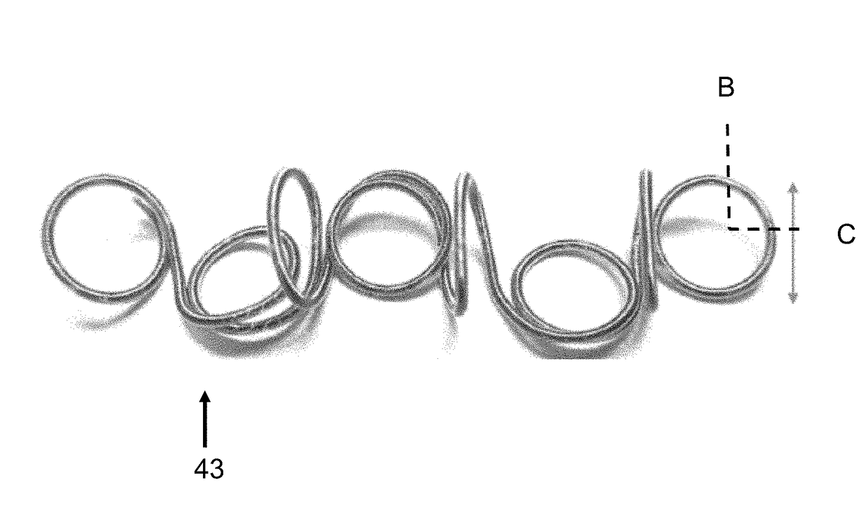
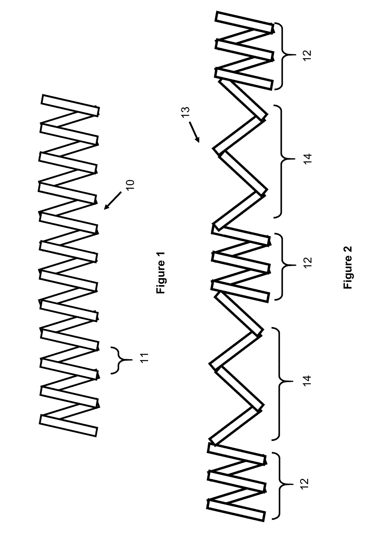
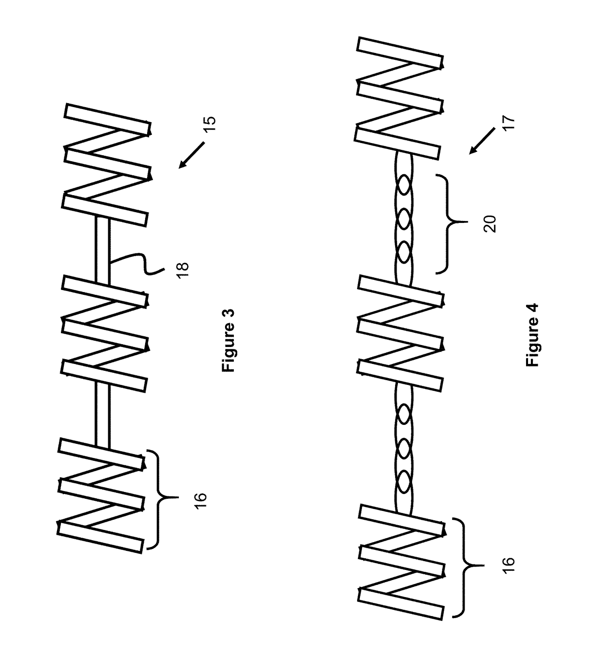
[0031]FIGS. 1-4 show various coil shape embodiments. The coils have particularly beneficial use as an injectable coil or as an injectable electropositive (e.g., tantalum) coil, but can also be used as a pushable coil. a coil 10 as shown in FIG. 1 is an open pitch coil (meaning there are gaps 11 between subsequent windings, instead of a closed pitch where there is no gap between windings) with a consistent shape. In one example, the coil may have a diameter of about 0.0005″ to about 0.00015″ for use in the neurovasculature and have a diameter of about 0.0015″ to about 0.003″ where used in the peripheral vasculature. In another embodiment, a closed pitch coil can be used where the sequential coil windings are nested together.
[0032]Another embodiment of a coil 13 is shown in FIG. 2. The coil is wound with a variable pitch where there is a closer wound section 12 utilizing closely spaced windings alternating with a stretched section 14 where the windings are not closely spaced. Such a c...
embodiment 21
[0036]FIG. 5 shows a chain embodiment 21 analogous to a jewelry chain comprising a series of enlarged elements 22 connected by a series of links 24. The elements 22 are referred to as “enlarged elements” to demarcate them from the smaller links. In one example the enlarged elements have an outer diameter of about 0.005″-0.30″ and length of about 0.01″-0.05″ and the links have a length of about 0.01″-0.05″. The enlarged elements can take on a number of shapes, (a non-inclusive list includes square, cylindrical, rectangular, spherical, ovular, and combinations therein). The enlarged elements are comprised of an electropositive material such as tantalum and the links can also be comprised of tantalum, or another metal—such as nitinol or stainless steel.
embodiment 23
[0037]FIG. 6 shows a chain embodiment 23 similar to the one of FIG. 5, with the only distinction being the inclusion of a series of spherical beads 26 in place of the enlarged elements 22 of FIG. 5. In one example the beads have a diameter of about 0.005″-0.03″ and the links have a length of about 0.003″-0.01″. The beads are comprised of an electropositive material such as tantalum.
PUM
 Abstract
Description
Claims
Application Information
 - R&D
- Intellectual Property
- Life Sciences
- Materials
- Tech Scout
- Unparalleled Data Quality
- Higher Quality Content
- 60% Fewer Hallucinations
Browse by: Latest US Patents, China's latest patents, Technical Efficacy Thesaurus, Application Domain, Technology Topic, Popular Technical Reports.
© 2025 PatSnap. All rights reserved.Legal|Privacy policy|Modern Slavery Act Transparency Statement|Sitemap|About US| Contact US: help@patsnap.com


