
Devices and Methods for Treatment of Endovascular and Non-Endovascular Defects in Humans Using Occlusion Implants

a technology of occlusion implants and human body, which is applied in the field of devices and methods for treating endovascular and non-endovascular defects in humans using occlusion implants, can solve the problems of affecting the thrombosis of the coil, the inability to deploy the plug, and the size of the plug, so as to facilitate deployment and retrieval, enhance the thrombogenicity of the implant, and enhance the radiopacity of the occlusion implant

Inactive Publication Date: 2017-02-09
HENRY NITA LLC
View PDF0 Cites 27 Cited by
  • Summary
  • Abstract
  • Description
  • Claims
  • Application Information

AI Technical Summary

Benefits of technology

The present invention provides occlusion implants that can be attached to a pusher and positioned inside a delivery catheter. The implants are made of an expanding tubular braid and a coil. When released from the pusher, the implant expands and forms a pre-shaped anchoring structure that results in larger space coverage, while the attached coil provides a final packing of the treatment area, leading to effective occlusion. The implant can also cause trauma to tissues at the treatment site, which can serve to initiate a localized healing and enhance growth of new patient tissue at the site.

Problems solved by technology

These defects cause a variety of symptoms, ranging from pain, weakness, headache, vision loss, stroke or death.
However, in many cases, a patient's condition may dictate that immediate cessation of blood flow is required.
Detachable balloons have previously been used for parent artery occlusion but were not successful because of leaking and unexpected deflation, leading to major complications.
Thus, trickling blood flow which occurs for several minutes while the patient's blood is coagulating around the mass of coils may lead to creation and migration of thrombus from the mass of coils.
Currently available plugs such as the Amplatzer vascular plug are difficult to deploy and are size-sensitive.
Also, the open-mesh construction of these vascular plugs may result in dislodgement of thrombus as it is forming on the plug, leading to downstream embolization of the occluded artery.
Mechanical embolization devices such as filters and traps have been proposed in the past to achieve parent artery occlusion and are disclosed in U.S. Pat. Nos. 3,874,388; 5,334,217; 4,917,089 and 5,108,420 among others, however, deployment of these devices and / or recapture into the delivery catheter is difficult, further limiting the effectiveness of these devices.
The force of the blood pressure against the weakened wall causes the wall to abnormally bulge or balloon outside.
Aneurysms, particularly cranial aneurysms, are a serious medical condition because they can apply undesired pressure to areas within the brain.
Additionally, there is always the possibility that the aneurysm may rupture or burst leading to serious medical complications including death.

Method used


Image

  • Devices and Methods for Treatment of Endovascular and Non-Endovascular Defects in Humans Using Occlusion Implants
  • Devices and Methods for Treatment of Endovascular and Non-Endovascular Defects in Humans Using Occlusion Implants
  • Devices and Methods for Treatment of Endovascular and Non-Endovascular Defects in Humans Using Occlusion Implants

Examples


Embodiment Construction

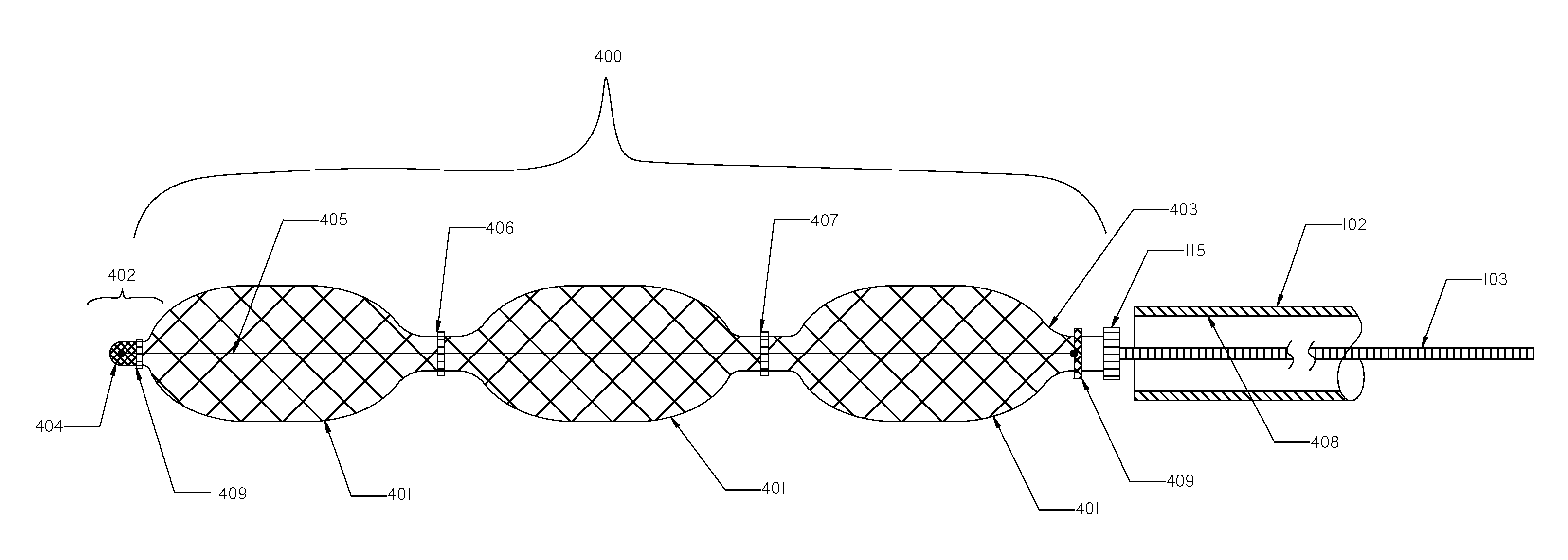
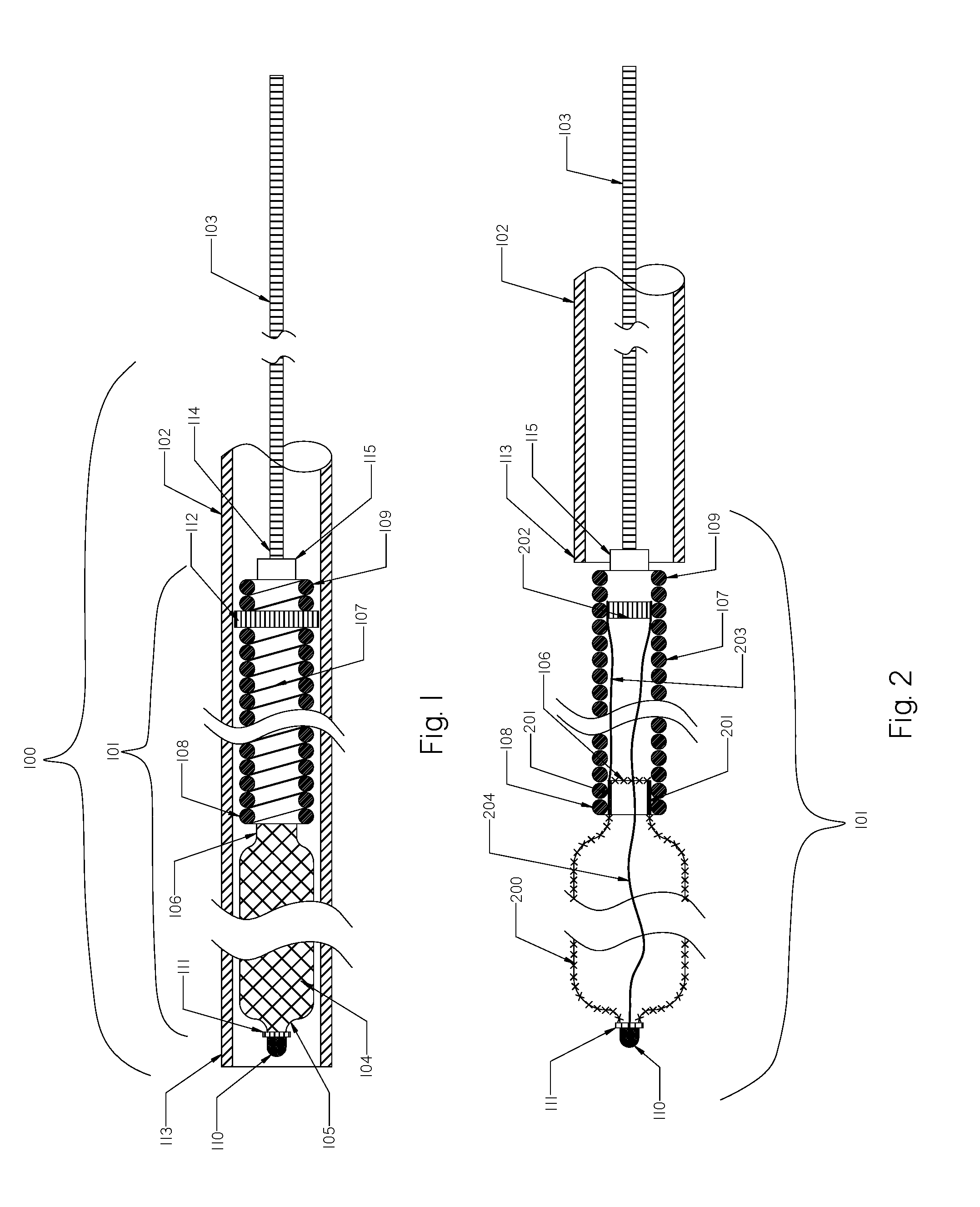
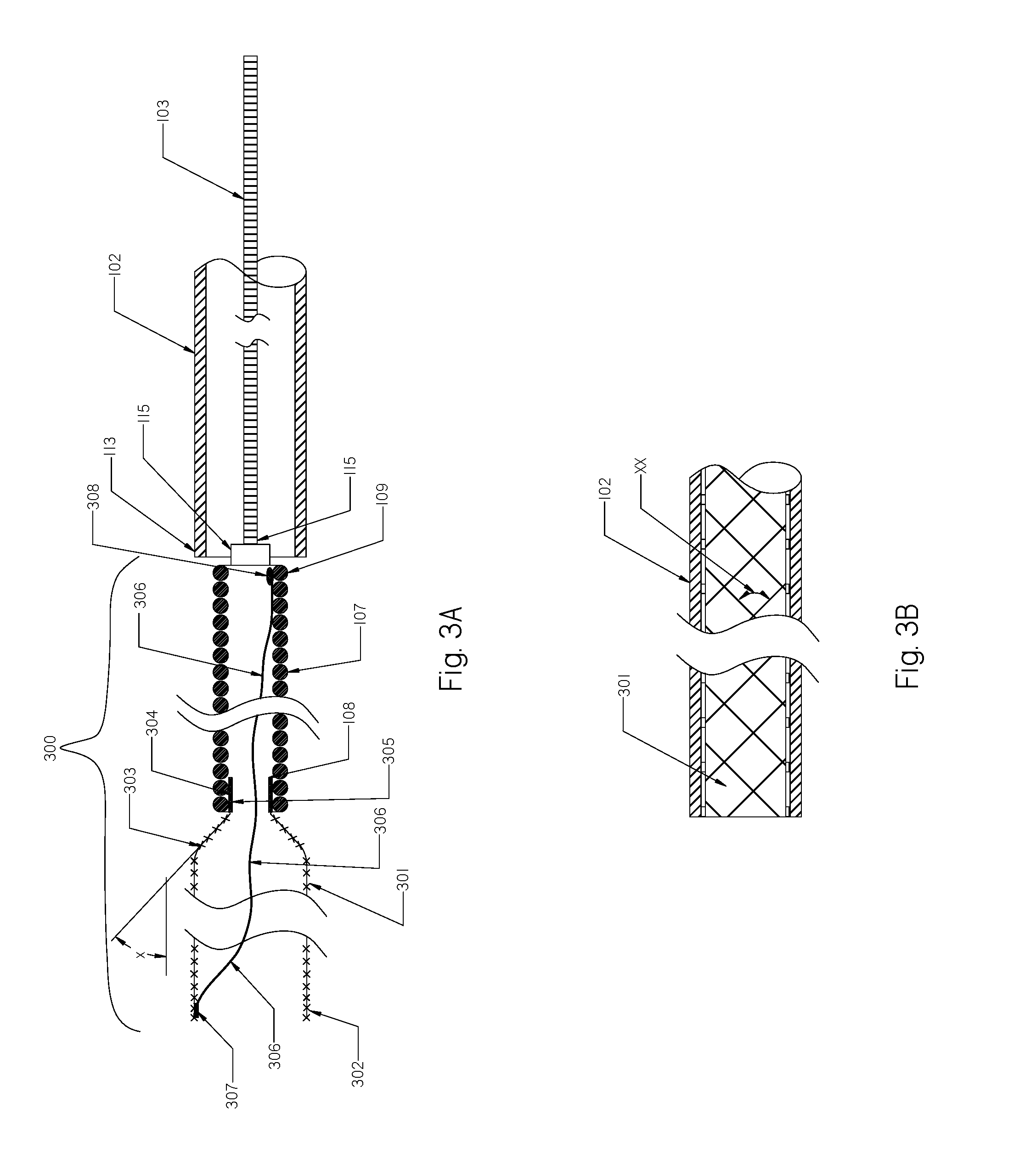
[0101]FIG. 1—Illustrates a schematic view of an occlusion device or system 100 with occlusion implant 101 inside the delivery catheter 102. The occlusion implant 101 is shown inside the delivery catheter 102 in a collapsed configuration. The occlusion device 100 comprises the occlusion implant 101, the delivery catheter 102, and the pusher member 103. The occlusion implant 101 comprises two elongate regions including the first distal region made of an expandable tubular braid 104 having a distal end 105 and the proximal end 106, and the second elongate region proximal to the first distal region comprised of a non-expandable helical coil 107 having the distal end 108 and proximal end 109. The tip 110 is formed on the distal end 105 of tubular braid 104 and prevents the very distal section of the braid 104 to fully expand when deployed from the delivery catheter 102. 100. The tip 110 may be made of one of the following materials: metal, polymer, rubber, adhesive or combination of all....


PUM


Abstract

Devices and methods are disclosed for occluding endovascular and non-endovascular defects, including parent artery occlusions, aneurysms and other abnormal openings in the body. The devices include one or more expandable braids that may be coupled to one or more helical coils suitable for introduction and retrieval from within a treatment area using a delivery catheter.

Description

RELATED CASES[0001]This application claims priority from: U.S. Provisional Patent Application No. 62 / 282,645, filed on Aug. 5, 2015; U.S. Provisional Patent Application No. 62 / 285,269 filed on Oct. 24, 2015; and U.S. Provisional Patent Application No. 62 / 283,730 filled on Sep. 9, 2015.PRIOR ART4,754,685July 1988Kite et al.4,820,298April 1989Leveen et al.4,870,887October 1989Tressiar et al.4,994,069February 1991Ritchart et al.5,186,992February 1993Kite5,217,484June 1993Marks5,304,194April 1994Chee et al.5,382,259January 1995Phelps etal.5,423,849June 1995Engelson et al.5,536,274July 1996Neuss5,639,277June 1997Mariant et al.5,690,667November 1997Gia5,792,157August 1998Mische et al.5,888,201March 1999Stinson et al.5,891,191April 1999Stinson5,964,797October 1999Ho5,976,162November 1999Doan et al.6,019,786February 2000Thompson6,024,754February 2000Engelson6,066,158May 2000Engelson et al.6,096,052August 2000Callister et al.6,165,178December 2000Bashiri et al.6,187,027February 2001Mariant e...

Claims


Application Information

Patent Timeline
Patent Type & Authority Applications(United States)
IPC IPC(8): A61B17/12A61B90/00
CPCA61B17/12172A61B17/12145A61B90/39A61B2017/1205A61B2090/3966A61B2017/00867A61B17/12109A61B17/12113A61B17/1214A61B17/12154A61B17/12163A61B2017/00526A61B2017/12054
Inventor SARGE, JEFFNITA, HENRY
Owner HENRY NITA LLC
Learn More