Printing apparatus

a printing apparatus and printing technology, applied in printing, other printing apparatus, typewriters, etc., can solve the problems of increasing the amount of mist afloat between the printing unit and the support base, the printing unit is not capable of achieving the effect, and the mist adhesion to the part of the support base supporting the medium is likely to permeate the absorbing material, etc., to achieve the effect of suppressing the adhesion of the part of the support base supporting the medium

Active Publication Date: 2017-07-06
SEIKO EPSON CORP
View PDF0 Cites 1 Cited by
  • Summary
  • Abstract
  • Description
  • Claims
  • Application Information

AI Technical Summary

Benefits of technology

[0049]The total amount of the liquid that the printing unit discharges to the medium when the printing ratio is high exceeds the total amount of the liquid that the printing unit discharges to the medium when the printing ratio is low, and thus the amount of the mist afloat between the printing unit and the support base increases after the printing termination.
[0050]According to this configuration, the rotation speed of the fan for suctioning the mist after the printing termination is increased in the case of a high printing ratio in this regard, and thus the mist afloat between the printing unit and the support base is likely to be suctioned into the recovery container. Accordingly, mist adhesion to the part of the support base supporting the medium can be suppressed.

Problems solved by technology

In addition, the mist adhering to the surface of the absorbing material is likely to permeate the absorbing material because of a change in the density of the absorbing material.
However, an increase in the liquid discharge amount leads to an increase in the amount of the mist afloat between the printing unit and the support base.
Accordingly, the printing unit is not capable of achieving the effect in the form of the suctioning of the mist into the recovery container being further facilitated to a sufficient extent, even if the rotation speed of the fan is increased, within a short period of time such as the length of time taken for the next medium to be transported onto the support base after the printing on the single surface of the medium is terminated.

Method used


Image

  • Printing apparatus
  • Printing apparatus
  • Printing apparatus

Examples


first embodiment

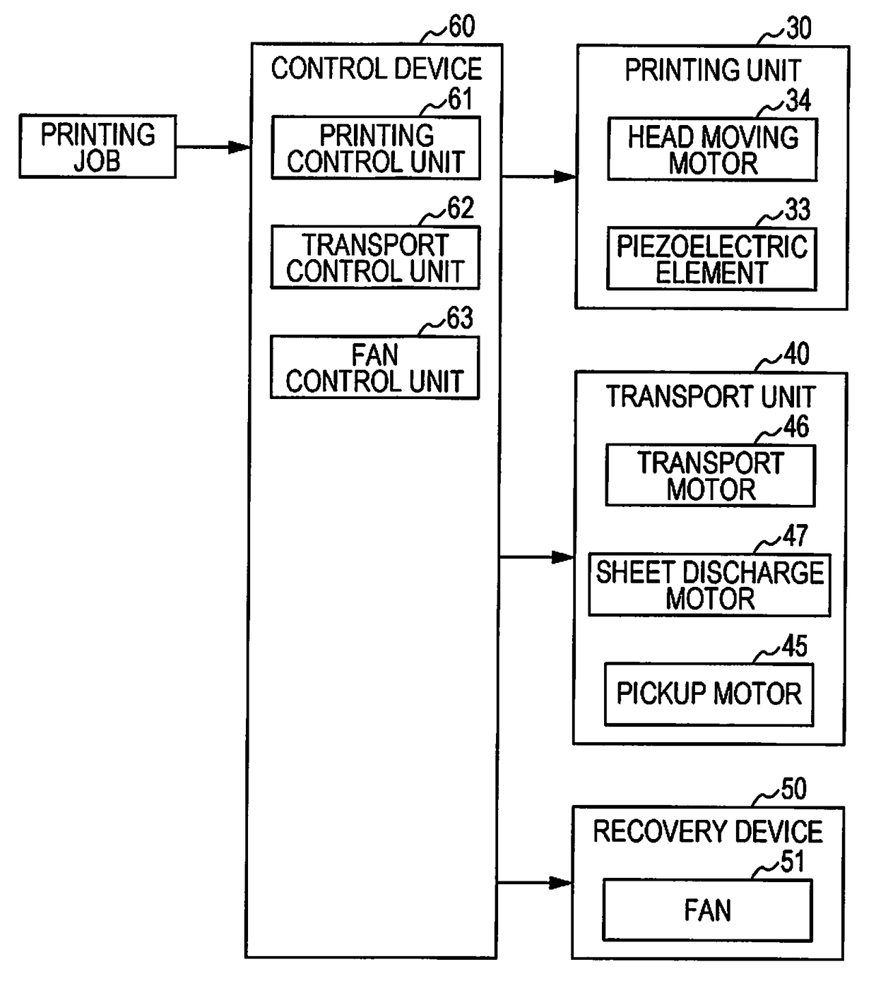
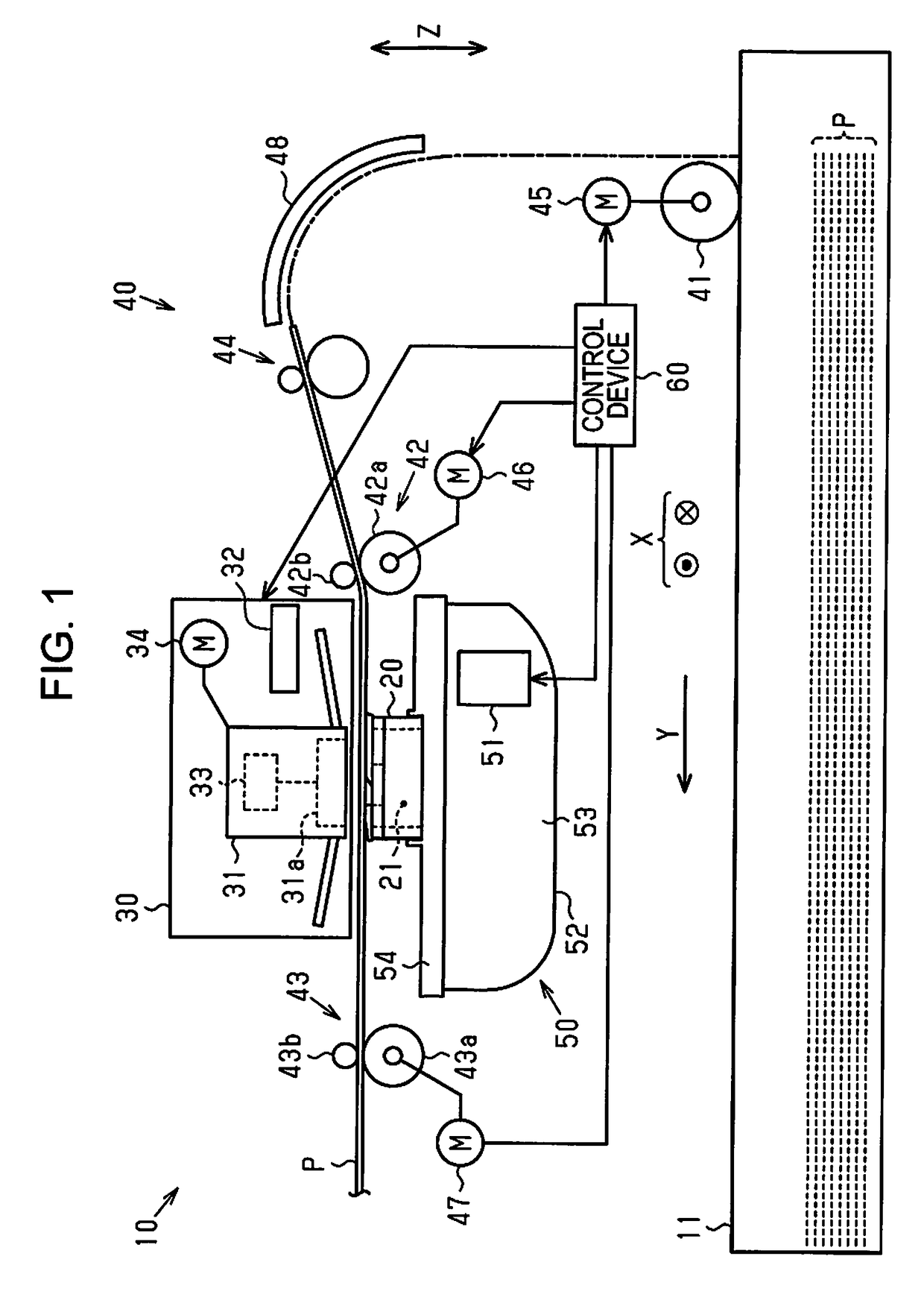
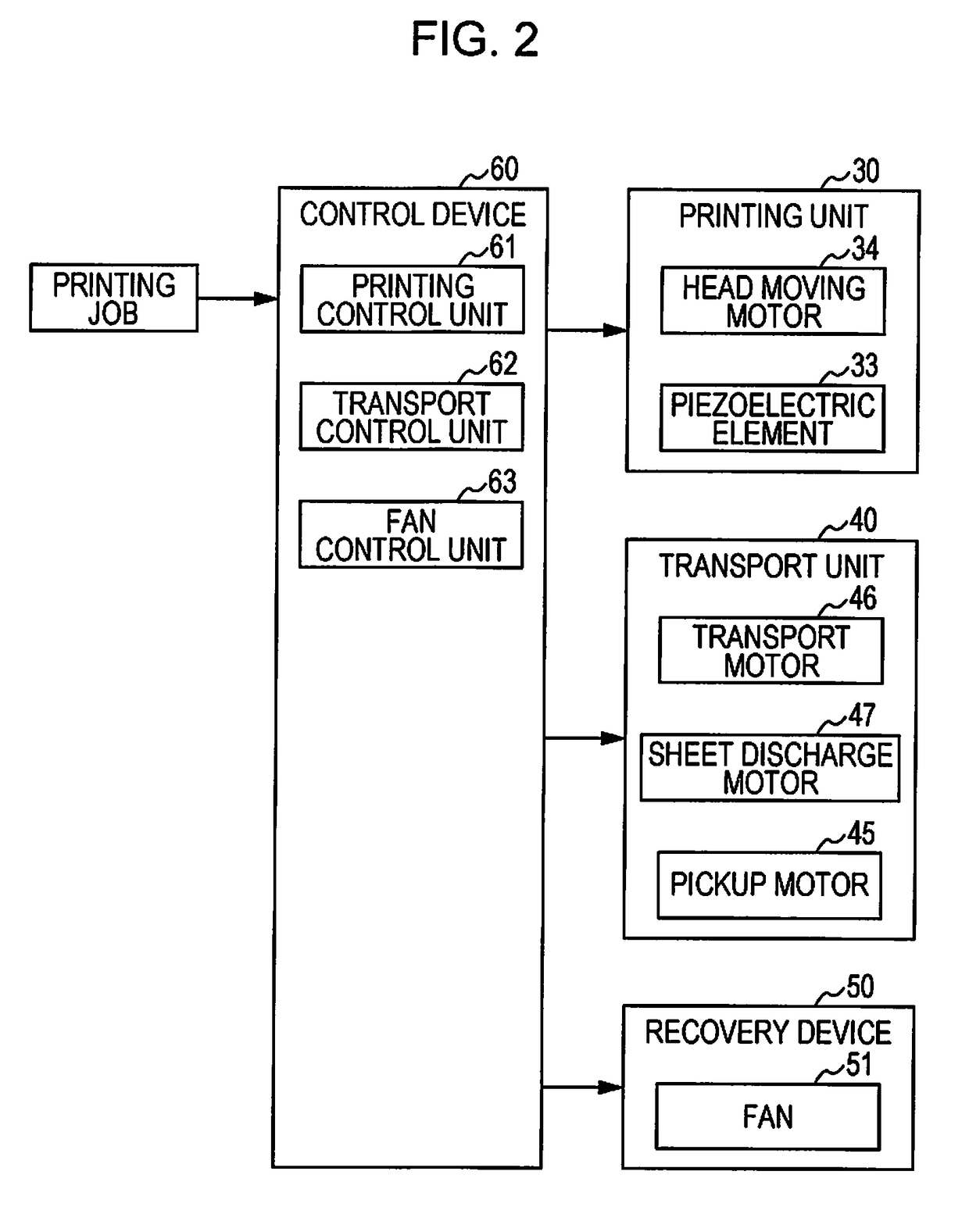
[0071]As illustrated in FIG. 1, a printing apparatus 10 is provided with a sheet cassette 11 that is capable of accommodating stacked sheets P, a support base 20 that supports the sheet P, a printing unit 30 that performs printing by discharging the ink to the sheet P transported onto the support base 20, and a transport unit 40 that transports the sheet P onto the support base 20. In addition, the printing apparatus 10 is provided with a recovery device 50 that recovers mist arising from the ink discharged from the printing unit 30 and a control device 60 that controls the printing unit 30, the transport unit 40, and the recovery device 50. In the following description, the width direction of the sheet P will be defined as a “width direction X” and a direction in which the sheet P is transported will be defined as a “transport direction Y”. The width direction X, which is an example of directions intersecting with the transport direction Y, is orthogonal to the transport direction ...

second embodiment

[0107]A printing apparatus 10 according to the second embodiment will be described with reference to FIGS. 10 to 12. The printing apparatus 10 according to the present embodiment differs from the printing apparatus 10 according to the first embodiment in that the rotation speed of the fan 51 (refer to FIG. 1) of the recovery device 50 can be variably controlled. In the following description, components of the printing apparatus 10 to which signs are attached represent the respective components of the printing apparatus 10 illustrated in FIGS. 1 to 7.

[0108]The control device 60 drives the fan 51 throughout, for example, a driving period following the termination of the printing job after the printing job is received. In other words, the fan 51 is driven during the flushing and the printing by the printing unit 30. In some cases, the flushing is executed before the initiation of the printing on the sheet P following the reception of the printing job and in the middle of the printing o...


PUM


Abstract

In a printing apparatus, ink mist resulting from ink discharge is suctioned by a fan and moves along a flow path (recovery path) formed by alternating ribs in a recovery unit, and the ribs have a width becoming increasingly smaller as a downstream side of the flow path (recovery path) is approached.

Description

BACKGROUND[0001]1. Technical Field[0002]The present invention relates to a printing apparatus that is provided with a recovery device which recovers mist arising from a liquid discharged from a printing unit.[0003]2. Related Art[0004]In the related art, a printing apparatus 100 illustrated in FIG. 17 is known as an example of this type of printing apparatus.[0005]In the printing apparatus 100, a recovery device 130 is disposed in the vicinity of a printing unit 120 and the recovery device 130 suctions mist by means of a fan 131 after the mist is generated from a liquid (ink) that is discharged from the printing unit 120 to a medium PR transported by a transport drum 110. A recovery container 132 of the recovery device 130 accommodates the fan 131 and a filter 133 placed upstream of the fan 131. The recovery device 130 suctions the mist from a suction port 134 formed in the recovery container 132 and recovers the mist by means of the filter 133 by driving the fan 131.[0006]In this re...

Claims


Application Information

Patent Timeline
Patent Type & Authority Applications(United States)
IPC IPC(8): B41J2/165
CPCB41J2/16517B41J2/185B41J2002/1853B41J2/16526B41J2/16585B41J3/407B41J2/1714B41J29/38
Inventor SUZUKI, YUTO
Owner SEIKO EPSON CORP
Why Eureka
Try Eureka