
Systems and Methods for Monitoring Roadways Using Magnetic Signatures

Active Publication Date: 2017-07-06
TOLLSENSE LLC
View PDF0 Cites 7 Cited by
  • Summary
  • Abstract
  • Description
  • Claims
  • Application Information

AI Technical Summary

Benefits of technology

The invention utilizes the magnetic field of the earth to monitor roadways and traffic using portable devices such as smartphones and tablets. It can accurately track vehicles and individuals using magnetometers, and can identify which roadway they are driving on by comparing magnetic signatures to a map. This solution does not require any additional infrastructure and can cost-effectively assess tolls. It provides reliable positioning accuracy within 1 to 3 feet, so it can distinguish between vehicles on different roads.

Problems solved by technology

Access to travel information on an individualized basis has been historically inaccurate and / or expensive to collect, aggregate, and analyze.
However, tollways have their drawbacks, not the least of which is the inefficient collection of tolls in a way that can adversely impact traffic.
The disadvantages of this are evident in that they require vehicles to slow down and / or stop to complete the payment transaction with a live employee that is stationed in the toll booth to collect the applicable toll, either in cash or by payment card.
Although these automatic toll collection systems are an improvement over manned toll booths, they still require large expenditures for both the electronic toll collection equipment and transponders for the vehicles in order to function.
However, the processing costs of identifying the vehicles that do not have transponders (e.g., on tollways that use a combination of photo and transponder technology) by cross referencing all of the vehicles that pass through a particular toll gate against those that have the appropriate transponder technology can be high.
Nor will the government agency charged with maintaining vehicle ownership information necessarily have current information on the actual owner of every vehicle in their state.
This process can be intentionally or unintentionally delayed, and in cases where the new owner uses tollways, the bill for those tolls would be assessed to the previous owner, most often through no fault of the tollway agency or the previous owner of the vehicle.
Even where electronic toll solutions are used, opportunities for theft of services and billing individuals for tolls they did not incur abound.
For example, theft of the transponders and subsequent use in vehicles not associated with the individual to which the transponder was issued can result in the billing of multiple tolls to the theft victims that is often compounded because the victim is not immediately aware that the transponder has been stolen.
Also, the risk that an RFID transponder may be cloned and used for illegal purposes is significant in view the technology available for those willing to engage in such illegal activities for profit.
Tolls charged to rental car companies that should properly be charged to the driver using the tollways also cause problems and significant transactional inefficiencies.
However, the accuracy of GPS is limited and depends on many factors (e.g., the quality of the GPS receiver, the position and number of GPS satellites, the characteristics of the transmission environment, the weather).
Further, even the most precise GPS will determine the position of the device within 10 feet under the most ideal conditions (e.g., not accounting for line of sight requirements or adverse environmental conditions).
Because tollways often run parallel to frontage roads that are not subject to tolls, the use of GPS to charge tools to vehicles as they move along the tollways can be problematic because the inherent inaccuracy of GPS systems could result in inadvertently and incorrectly charging tolls to vehicles traveling along a frontage road.

Method used


Image

  • Systems and Methods for Monitoring Roadways Using Magnetic Signatures
  • Systems and Methods for Monitoring Roadways Using Magnetic Signatures
  • Systems and Methods for Monitoring Roadways Using Magnetic Signatures

Examples


Embodiment Construction

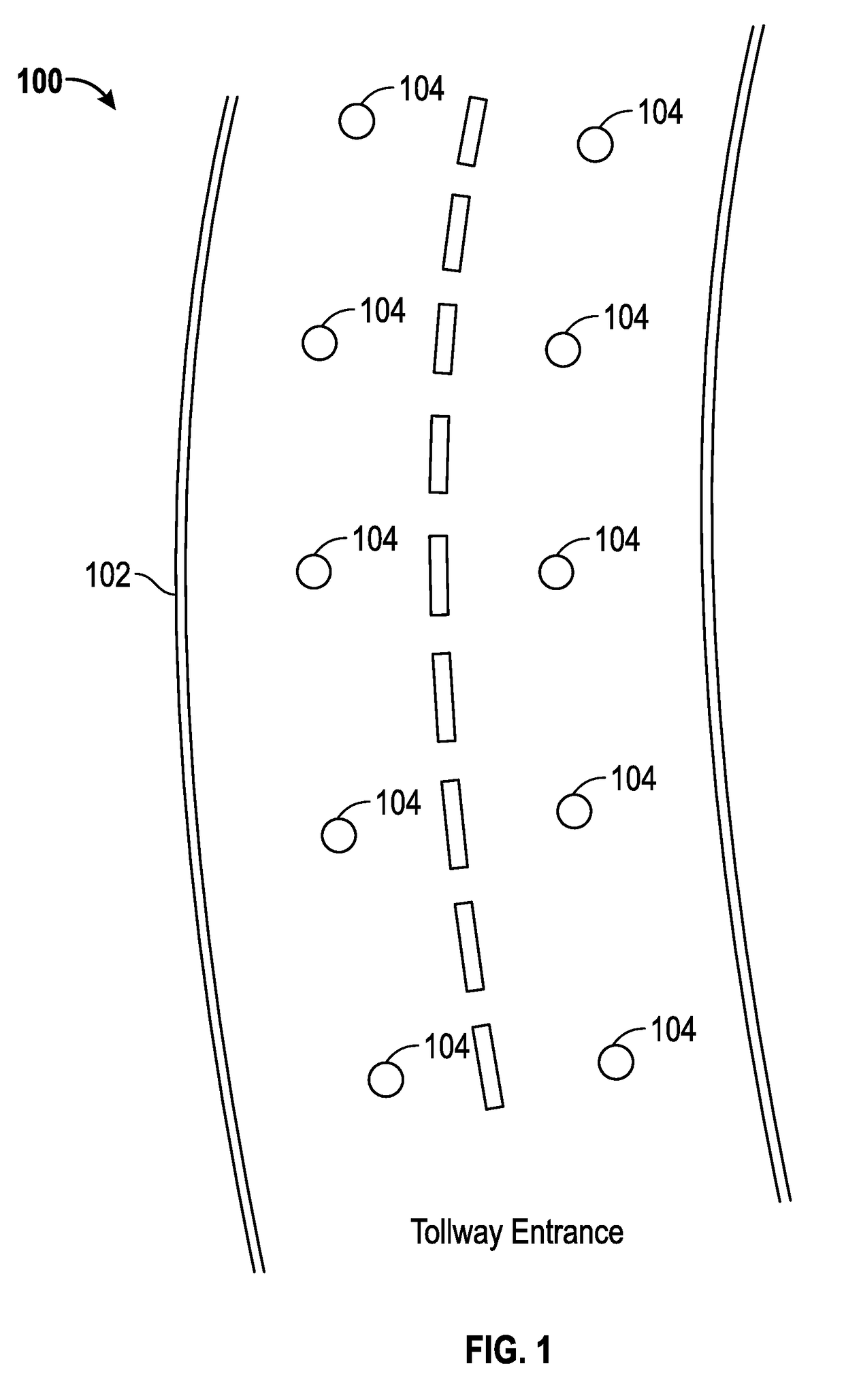
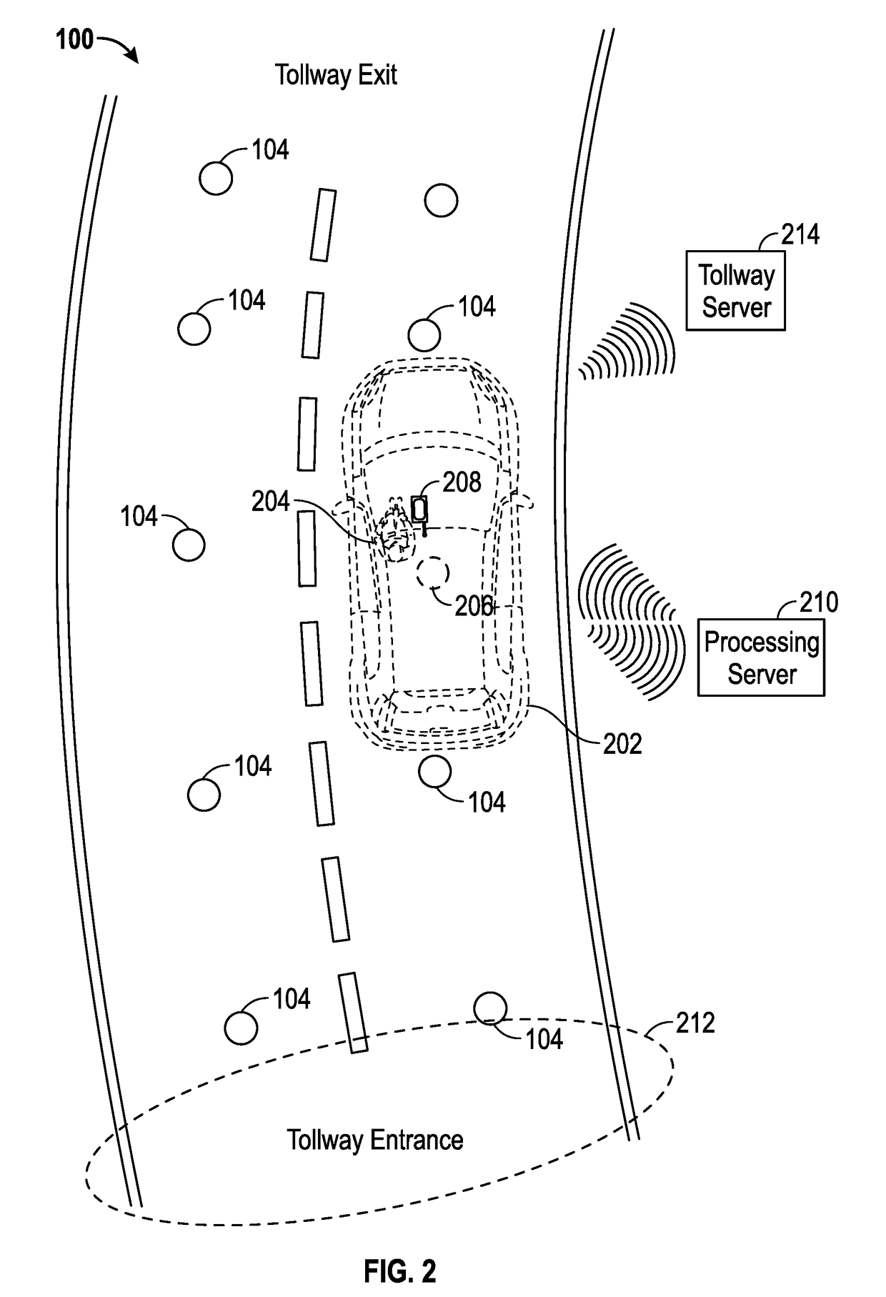
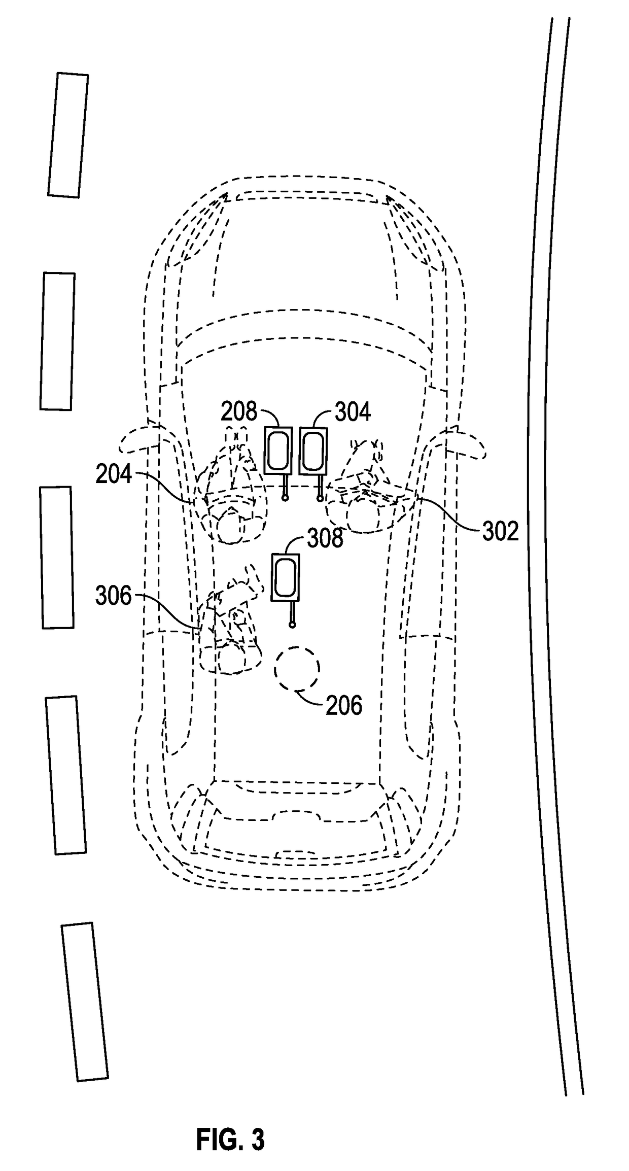
[0021]Devices equipped with magnetometers are able to identify unique geomagnetic signatures for every position on the Earth. A magnetometer generally measures the direction of its position from the magnetic North Pole and the strength of the Earth's magnetic field at that location. The combination of the heading and strength measurements at a particular location is often referred to as the geomagnetic signature or magnetic fingerprint of that physical location. While latitude and longitude values are unique in their identification of points on the Earth, magnetometer heading and strength values are theoretically capable of repeating at various points on the Earth. Therefore, because magnetometer measurements are not guaranteed to be unique across every point on the Earth (e.g., the strength of the magnetic field across the Earth changes in a non-linear fashion), reliability of their use for location identification applications is improved by utilizing them in a system in which geom...


PUM


Abstract

A system and method are disclosed for using magnetic signatures at predetermined positions along a roadway to monitor traffic travelling along the roadway by comparing the predetermined magnetic signatures with magnetic signatures being dynamically and continuously measured by each vehicle as they travel along the roadway. Magnetometers incorporated into mobile devices or otherwise incorporated within the vehicle measure magnetic signatures for comparison to the predetermined magnetic signatures that form a connection graph or database of points that correspond to possible paths along a roadway. When a magnetic signature match is made, the system recognizes that the vehicle has passed a particular point on a roadway and forwards that information to the appropriate entity for further processing, analysis, or toll assessment.

Description

TECHNICAL FIELD[0001]The present invention relates generally to the use of magnetic signatures to accurately monitor roadways.BACKGROUND OF THE INVENTION[0002]It is axiomatic that the ability to accurately monitor roadways and the vehicles that travel upon them can provide vital information to public or private entities that are charged with building, developing, maintaining, and managing the roadway systems to improve traffic conditions and plan for future transportation needs. Understanding the nature of traffic patterns on a macro level allows the responsible entities to evaluate and approve construction projects designed to alleviate problems in areas where traffic congestion is especially troublesome. Access to travel information on an individualized basis has been historically inaccurate and / or expensive to collect, aggregate, and analyze. Because of the inherent need to assess tolls for users of certain publicly-financed roads, much of the progress in this area has been made ...

Claims


Application Information

Patent Timeline
IPC IPC(8): G08G1/042G08G1/01G08G1/052
CPCG08G1/042G08G1/0116G08G1/0125G08G1/052G08G1/0112G08G1/0129G08G1/056G07B15/06G07B15/063
Inventor BARANGA, ALEXGEORGIEFF, CHRISGILMORE, MICHAELWARD, THOMAS
Owner TOLLSENSE LLC
Learn More