Method and Control Device for Automatically Determining a Mass of a Door System

Inactive Publication Date: 2010-01-21
SIEMENS AG
View PDF1 Cites 2 Cited by
  • Summary
  • Abstract
  • Description
  • Claims
  • Application Information

AI Technical Summary

Benefits of technology

[0008]It is the object of the invention to simplify the generic method for mass determination such that it is possibl

Problems solved by technology

It is disadvantageous of the two methods that in the case, for example, of two-leaf doors with a very small opening width, only half an opening width is available for mass determination for a driving operation.
This short distan

Method used


Image

  • Method and Control Device for Automatically Determining a Mass of a Door System
  • Method and Control Device for Automatically Determining a Mass of a Door System
  • Method and Control Device for Automatically Determining a Mass of a Door System

Examples


Embodiment Construction

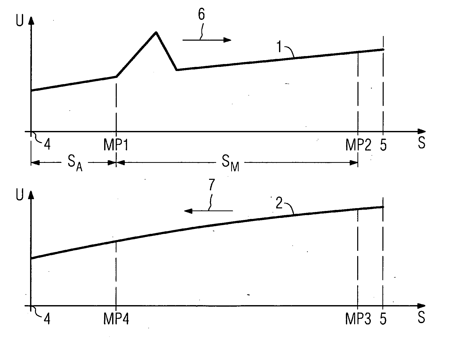
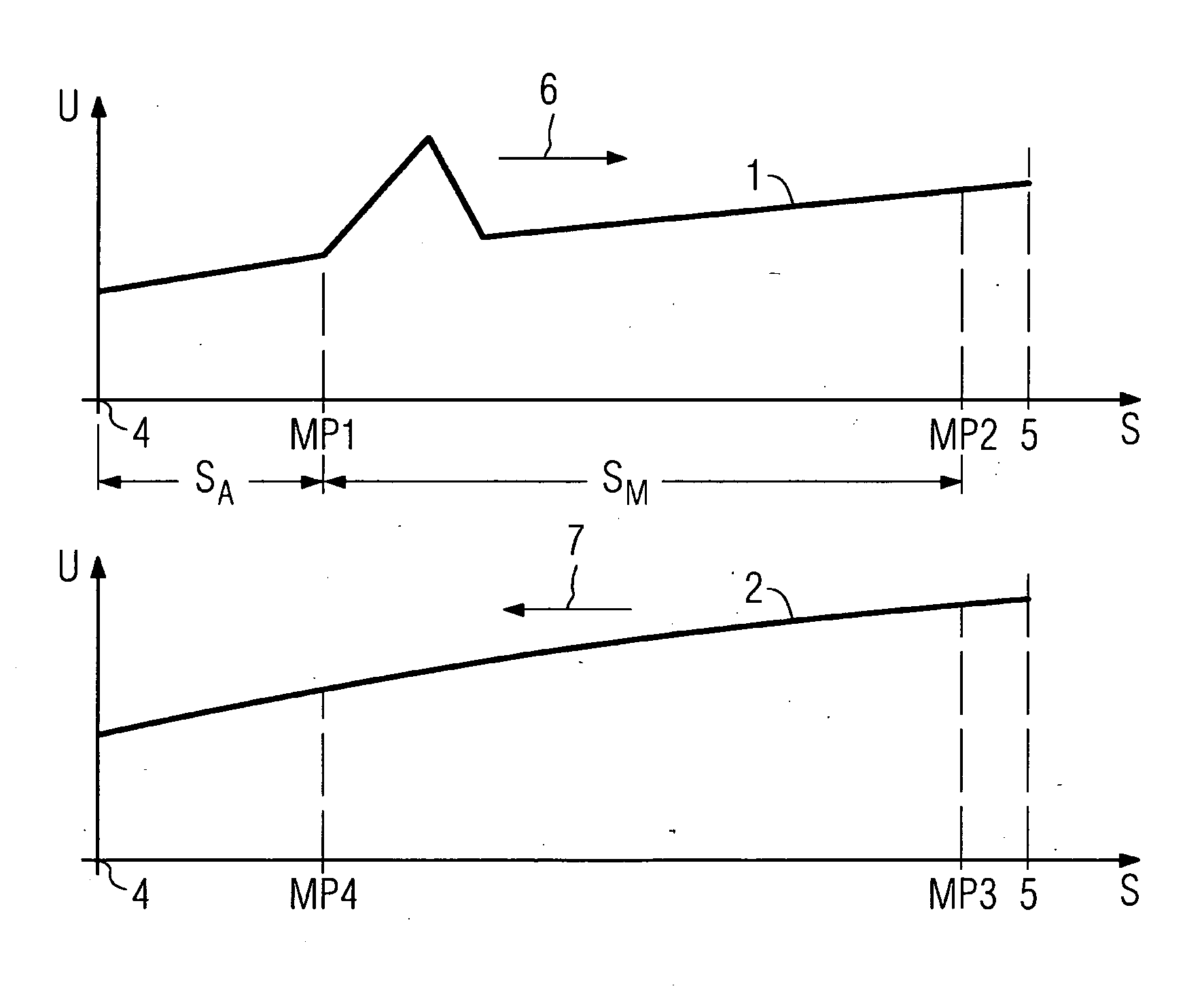
[0026]The sole FIGURE respectively shows a motor voltage profile 1 and 2 for an electrically driven door with a mass mT. A motor voltage U is respectively plotted over a movement distance S. The motor voltage profile 1 is illustrated over the movement distance S for a movement in the opening direction 6. The motor voltage profile 2 is illustrated over the movement distance S for a movement in the closing direction 7.

[0027]The door is closed at position 4, this corresponding to a movement distance S=0 mm. After a run up distance of preferably SA=100 mm, starting from a first instant or measuring point MP1 a total current IG is measured for the movement distance of a motor voltage ramp present for 40 operating system cycles Δt with a gradient of one pulse width modulation increment per operating system cycle Δt. A motor current I is summed for this time duration. The motor current I is composed of the measured total current IG minus a friction current IR, I=IG−IR. The door is complete...


PUM


Abstract

A method is disclosed for automatically determining an effective mass of a door system that is driven by a motor and has at least one door. In this case a speed change accomplished during an acceleration movement is established, and a force variable, for example the motor current or an armature voltage, influencing the drive force of the motor is summed or integrated during the acceleration movement. The effective door mass is established from the sum or the integral of the force variable and the speed change, the summation or the integration of the force variable being performed over a number of operating system cycles of a control device assigned to the door system. Also described is a control device for automatically determining the effective door mass, having a memory for force variable profiles that is designed in such a way that mass can be established for different force variable profiles in the memory in conjunction with an unchanged program code.

Description

CROSS REFERENCE TO RELATED APPLICATIONS[0001]This application is the US National Stage of International Application No. PCT / EP2006 / 067337, filed Oct. 10, 2006 and claims the benefit thereof. The International Application claims the benefits of German application No. 10 2005 050 125.7 filed Oct. 18, 2005, both of the applications are incorporated by reference herein in their entirety.FIELD OF INVENTION[0002]The invention relates to a method for automatically determining a mass (meff) of a door system that is driven by a motor and has at least one door, a speed change accomplished during an acceleration movement being established, and a force variable influencing the drive force of the motor being summed or integrated during the acceleration movement, and the sum or the integral of the force variable and the speed change (ΔV) being used to determine the mass (meff).[0003]The term door is to be understood equally as a single door leaf, a double door leaf and a rolling door with closing...

Claims


Application Information

Patent Timeline
IPC IPC(8): G05B19/042
CPCB66B13/146
Inventor KRAUSE, UWELUDWIG, HEINZNOLTE, UWESONNTAG, GUIDO
Owner SIEMENS AG
Why Eureka
Try Eureka