Check patentability & draft patents in minutes with Patsnap Eureka AI!

Liquid crystal display and method of manufacturing thereof

a technology of liquid crystal display and liquid crystal, which is applied in the field of liquid crystal display (lcd), can solve the problems of gap mura of tft lcd, low yield rate of tft lcd, and adverse effects of tft lcd yield

Active Publication Date: 2017-07-13
TCL CHINA STAR OPTOELECTRONICS TECH CO LTD
View PDF9 Cites 1 Cited by
  • Summary
  • Abstract
  • Description
  • Claims
  • Application Information

AI Technical Summary

Benefits of technology

The present invention is a method for making a liquid crystal display by creating a barrier wall at a non-active area of a substrate, and then injecting liquid material to form an alignment film at the active area of the substrate. This results in an alignment film that extends outward to reach the barrier wall. The technical effect of this method is to improve the manufacturing process of liquid crystal displays.

Problems solved by technology

Such an uneven thickness of the alignment film can cause the TFT LCD to have problems of gap mura.
Accordingly, the yield rate of the TFT LCD is adversely affected and low.
When this happens, the liquid PI 14 can reach the sealant to contaminate the sealant, which may result in a peeling-up of the sealant.

Method used


Image

  • Liquid crystal display and method of manufacturing thereof
  • Liquid crystal display and method of manufacturing thereof
  • Liquid crystal display and method of manufacturing thereof

Examples


Embodiment Construction

[0032]The structure and the technical means adopted by the present invention to achieve the above and other objects can be best understood by referring to the following detailed description of the preferred embodiments and the accompanying drawings. The terms used in the specification such as “up”, “down”, “front”, “rear”, “left”, “right”, “inward”, “outward” and “lateral”, etc. are the directions of the accompanying drawings. Such directions are used to better understand the invention, not used to limit the invention.

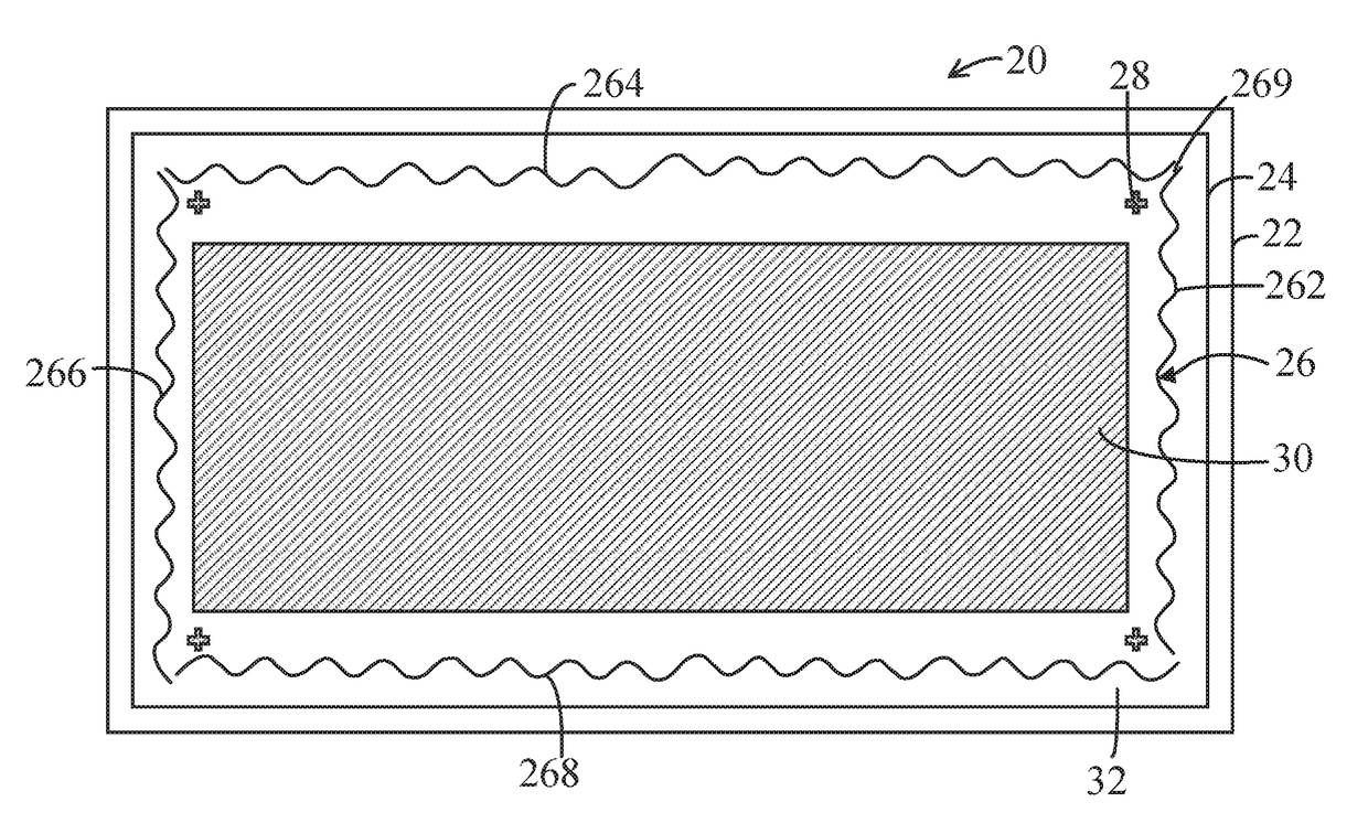
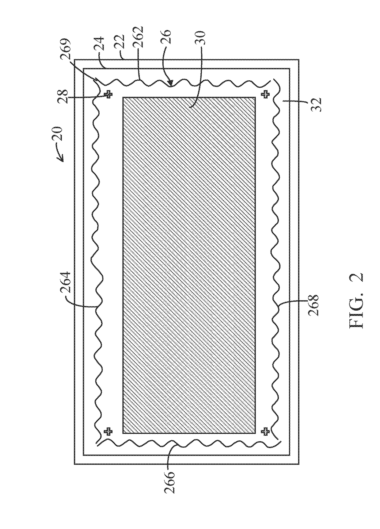
[0033]The present invention is proposed to solve the problems of the uneven thickness of the alignment film and that the applied liquid PI may overflow the barrier wall to cause the liquid PI to reach the sealant. Referring to FIG. 2, it shows a substrate 20 constructed in accordance with the present invention. The substrate 20 can be an array substrate or a color filter. In the preferred embodiment, the substrate 20 is an array substrate. The array substrate 20 has an...


PUM

PropertyMeasurementUnit
areaaaaaaaaaaa
electrical fieldaaaaaaaaaa
heightaaaaaaaaaa

Abstract

A liquid crystal display includes a substrate defining an active area and a non-active area surrounding the active area, a sealant located on the non-active area for hermetically connecting with another substrate to seal a crystal liquid layer between the substrate and the another substrate, and an alignment film barrier wall formed on the non-active area and located between the sealant and the active area. The barrier wall has a wave-shaped configuration consisting of protrusions projecting toward the active area and recesses recessed from the active area. When liquid polyimide is applied to the substrate to from an alignment film, the liquid polyimide is injected at fronts of the protrusions; then the liquid polyimide flows along the wave-shaped barrier wall to enter the recesses thereof.

Description

FIELD OF THE INVENTION[0001]The present invention relates to a liquid crystal display (LCD) and method of manufacturing thereof, and, in particular, to a structure of a barrier wall for forming an alignment film of an LCD, and a method for forming the alignment film.BACKGROUND OF THE INVENTION[0002]Liquid crystal displays (LCDs), particularly, thin film transistor LCDs (TFT LCDs) have become the main products of the flat displays presently available in the market. The TFT[0003]LCD has become an important display platform for the present information appliance and audio / video system.[0004]A TFT LCD basically includes an array substrate, a color filter and a liquid crystal layer located between the array substrate and the color filter. When the characteristics of electrical field between the array substrate and the color filter change, the liquid crystal molecules in the liquid crystal layers which guides light transmission from the array substrate to the color filter are twisted with ...

Claims


Application Information

Patent Timeline
Patent Type & Authority Applications(United States)
IPC IPC(8): G02F1/1337G02F1/1335G02F1/1339
CPCG02F1/133711G02F1/133514G02F1/13394G02F1/1339G02F1/133707G02F1/133723G02F1/1337
Inventor HUANG, SHISHUAI
Owner TCL CHINA STAR OPTOELECTRONICS TECH CO LTD
Features
  • R&D
  • Intellectual Property
  • Life Sciences
  • Materials
  • Tech Scout
  • Unparalleled Data Quality
  • Higher Quality Content
  • 60% Fewer Hallucinations
Learn More