Control system, image forming system, control method, and computer-readable recording medium

Active Publication Date: 2017-07-13
RICOH KK
View PDF4 Cites 7 Cited by
  • Summary
  • Abstract
  • Description
  • Claims
  • Application Information

AI Technical Summary

Benefits of technology

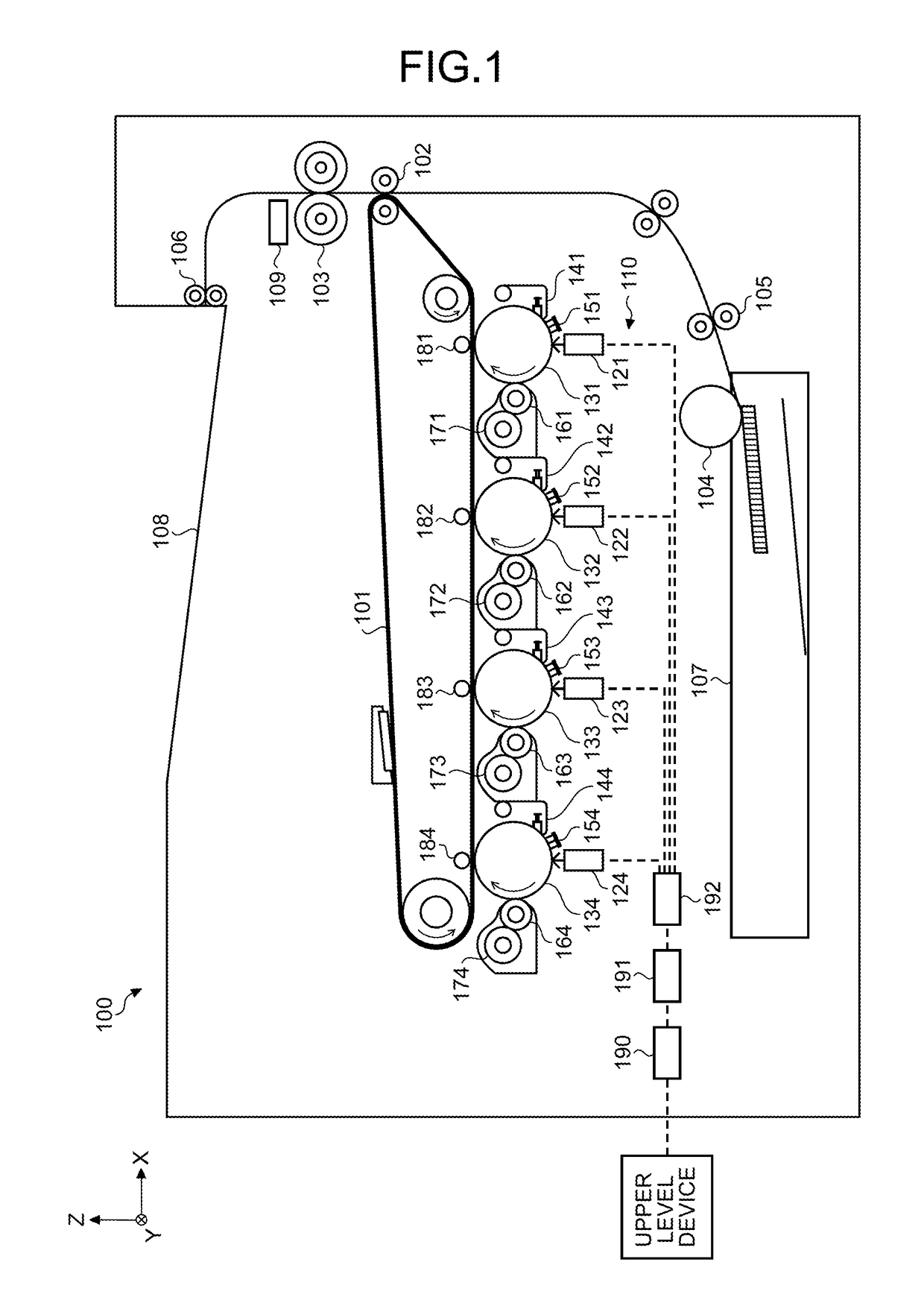
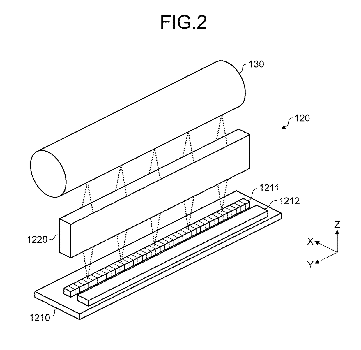
[0010]According to one aspect of the present invention, a control system controls an image forming unit that includes a charging device, an image bearer to be charged by the charging device, a light-emitting device array including a plurality of light emitting devices, and a driving causing the light emitting devices to emit light to form a latent image on the image bearer. The control system includes a light-amount-correction-value storage unit, a light-amount corrector, and a controller. The light-amount-correction-value storage unit i

Problems solved by technology

Problems that is concerned about when the light-emitting device array is used in the image forming apparatus are variation in optical output of the multiple light emitting diodes in the light-emitting device array caused at the time of manufacturing the light-emitting device array, and nonuniformity in light amount caused by an assembly error and the like of each light emitting device and an equal-magnification image forming device (rod lens array).
The nonuniformity in light amount can cause deterioration of an image, and can appear as vertical streaks in an image printed out.
Furthermore, deterioration of an image can include an image skew and the like caused by deviation of a main/sub image position due to an asse

Method used


Image

  • Control system, image forming system, control method, and computer-readable recording medium
  • Control system, image forming system, control method, and computer-readable recording medium
  • Control system, image forming system, control method, and computer-readable recording medium

Examples


Example

[0039]The terminology used herein is for the purpose of describing particular embodiments only and is not intended to be limiting of the present invention.

[0040]As used herein, the singular forms “a”, “an” and “the” are intended to include the plural forms as well, unless the context clearly indicates otherwise.

[0041]In describing preferred embodiments illustrated in the drawings, specific terminology may be employed for the sake of clarity. However, the disclosure of this patent specification is not intended to be limited to the specific terminology so selected, and it is to be understood that each specific element includes all technical equivalents that have the same function, operate in a similar manner, and achieve a similar result.

[0042]An embodiment of the present invention will be described in detail below with reference to the drawings.

[0043]An object of an embodiment is to provide a control system, an image forming system, a control method, and a computer-readable recording...


PUM


Abstract

A control system controls an image forming unit that includes a charging device, an image bearer to be charged by the charging device, a light-emitting device array including a plurality of light emitting devices, and a driving causing the light emitting devices to emit light to form a latent image on the image bearer. The control system includes a storage unit, a corrector, and a controller. The storage unit is configured to store a light-amount correction value of each of the light emitting devices. The corrector is configured to correct a pixel value of each pixel in image data, based on the light-amount correction value of each light emitting device stored in the storage unit. The controller is configured to control the driver to cause each light emitting device to emit light based on image data for which a pixel value of each pixel has been corrected.

Description

CROSS-REFERENCE TO RELATED APPLICATION[0001]The present application claims priority under 35 U.S.C. §119 to Japanese Patent Application No. 2016-002750, filed Jan. 8, 2016. The contents of which are incorporated herein by reference in their entirety.BACKGROUND OF THE INVENTION[0002]1. Field of the Invention[0003]The present invention relates to a control system, an image forming system, a control method, and a computer-readable recording medium.[0004]2. Description of the Related Art[0005]Conventionally, in an image forming apparatus that prints an image on a recording medium through an image bearer, components that respectively perform charging, exposure, development, and transfer, is provided around the image bearer, and an image forming unit that performs a series of image forming (also referred to as “printing” or “recording”) processing including image forming is provided. Moreover, in such an image forming apparatus, a light-emitting device array in which plural light emitting...

Claims


Application Information

Patent Timeline
IPC IPC(8): B41J2/385H04N1/028H04N1/407H04N1/60H04N1/29H04N1/031
CPCH04N1/295H04N1/02845G03G15/043H04N1/407H04N1/6008H04N1/0312G03G15/04054H04N1/4015
Inventor SHIRAISHI, NAOTOKOBAYASHI, SHINJI
Owner RICOH KK
Why Eureka
Try Eureka