Electroacoustic Transducer

a transducer and electroacoustic technology, applied in the direction of electric transducers, diaphragm construction, electrical apparatus, etc., can solve the problems of weak construction, low durability of coupled parts, narrow directivity over the high frequency range, etc., to achieve wide directivity, high durability, and reliable vibration transmission

Active Publication Date: 2017-07-13
YAMAHA CORP
View PDF2 Cites 4 Cited by
  • Summary
  • Abstract
  • Description
  • Claims
  • Application Information

AI Technical Summary

Benefits of technology

[0019]These inventions enable reliable transmission of vibration between the diaphragm and the voice coil (e.g., the converter).
[0020]The electroacoustic transducer according to the one or more embodiments of the present invention is advantageous in numerous ways, for example, it can reproduce and pick up sounds with wide directivity. Moreover, the diaphragm and the voice coil (e.g., the converter) can be firmly fixed to each other with high durability. Vibration can be transmitted with a small loss, resulting in reliable transmission of vibration between the diaphragm and the voice coil (e.g., converter).

Problems solved by technology

However, in the case where sounds over a wide audible frequency range are reproduced by a single speaker unit, directivity is not uniform between a high frequency range and a low frequency range, resulting in narrow directivity over the high frequency range.
In such a riffell speaker, however, since the coupled portion of the membranes extends straight, the coupled portion of the membranes and a circular voice coil are coupled to each other at only two positions, resulting in a weak construction.
Thus, the coupled portions have low durability, and transmission of vibration is not reliable.
However, this increase is not sufficient, and further improvement is required.

Method used


Image

  • Electroacoustic Transducer
  • Electroacoustic Transducer
  • Electroacoustic Transducer

Examples


first embodiment

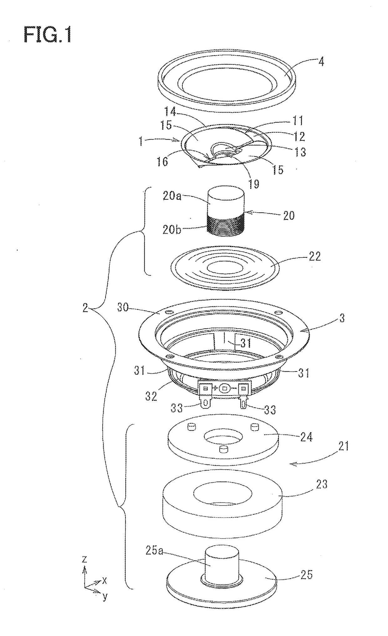
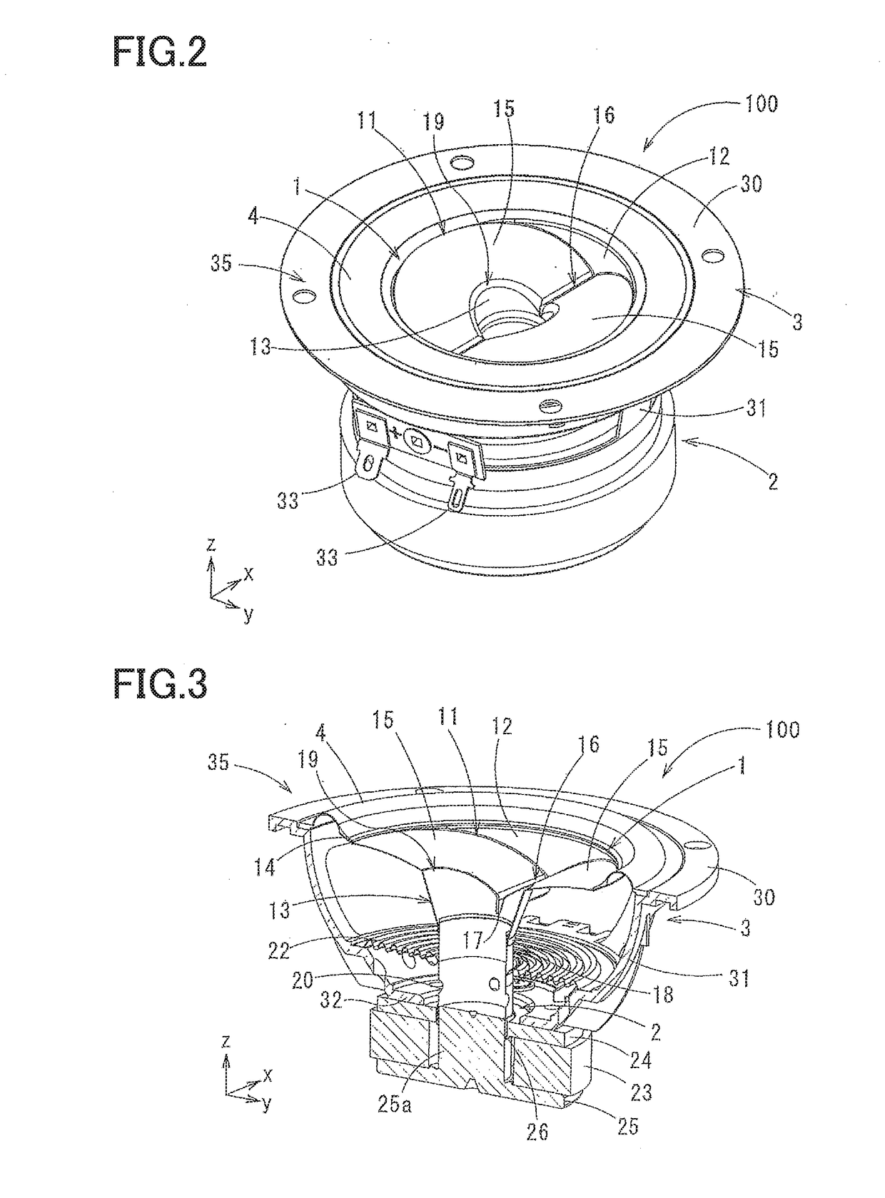
[0042]FIGS. 1-7 illustrate a speaker (e.g., an electric acoustic device) 100 according to the present invention.

1. Overall Construction

[0043]The speaker 100 according to this embodiment includes: a diaphragm 1; an actuator 2 (as one example of a converter in the present invention) for reciprocating the diaphragm 1; a support frame 3 for supporting the diaphragm 1 and the actuator 2; and an edge member 4 for supporting the diaphragm 1 such that the diaphragm 1 is reciprocable relative to the support frame 3.

[0044]In the state illustrated in FIGS. 1 and 2, the up and down direction is defined such that the upper side is a side on which the edge member 4 is provided, and the lower side is a side on which the actuator 2 is provided. The direction in which a valley of the diaphragm 1, which will be described below, extends is defined as the front and rear direction. The direction orthogonal to this direction is defined as the right and left direction. Surfaces facing upward may be referr...

third embodiment

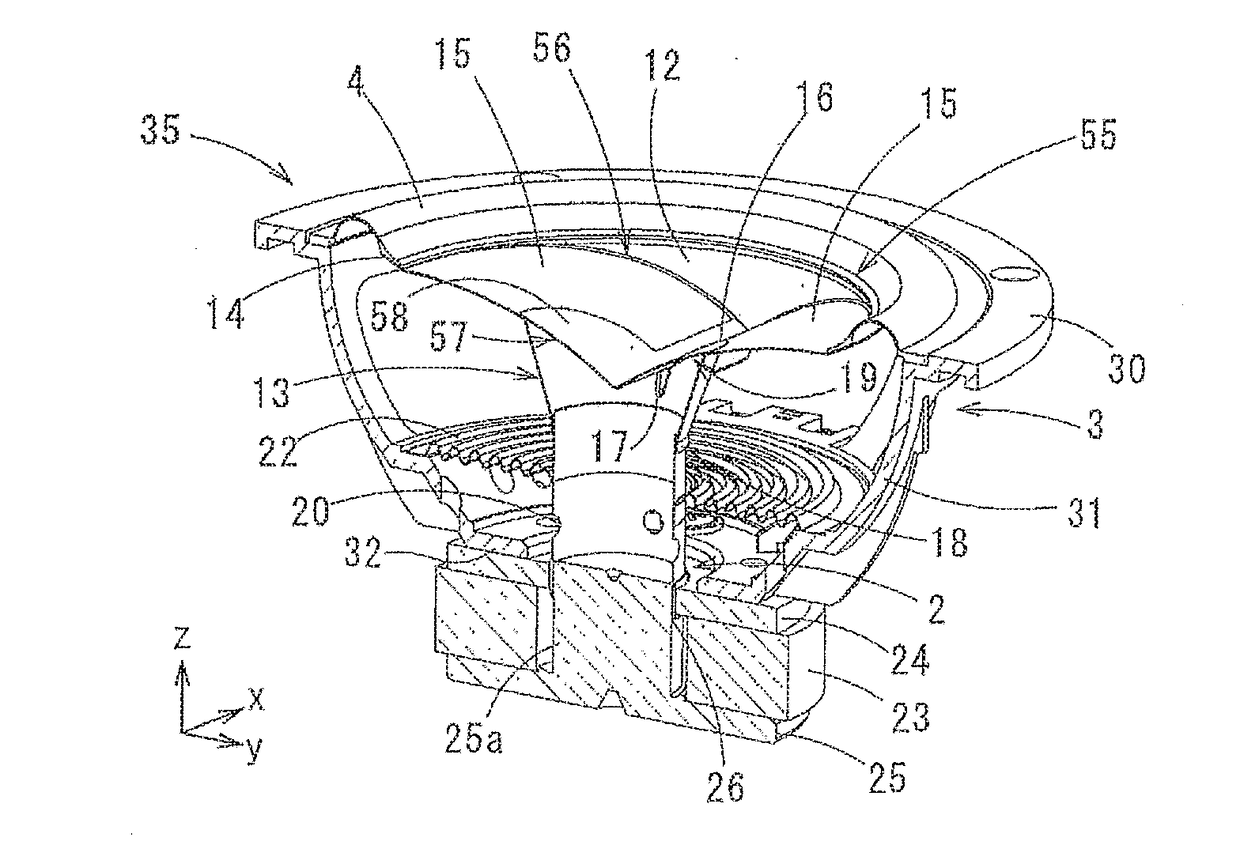
[0078]FIGS. 9 and 10 illustrate a speaker (an electroacoustic transducer) 300 according to the present invention.

[0079]In the diaphragm in the first embodiment and the second embodiment, an upper side of the valley 16 of the wing-pair portion and the tubular portion 13 is open, and a recessed space is formed over the valley 16 and the tubular portion 13. In a diaphragm 55 in the third embodiment, a closing plate (as one example of a cap member in the present invention) 57 is provided so as to close the through hole 19 formed in a wing-pair portion 56, that is, the closing plate 57 is provided so as to close a bottom portion of the valley 16 of the wing-pair portion 56 (the U-shaped portion in cross section) and an upper end of the tubular portion 13. A surface of this closing plate 57 has a valley-folded shape such that the longitudinal split tubular surfaces 15 of the wing-pair portion 56 are extended. The closing plate 57 has a pair of longitudinal split tubular surfaces 58 curved...

fourth embodiment

[0081]FIGS. 11 and 12 illustrate a speaker (an electroacoustic transducer) 400 according to the present invention.

[0082]In a diaphragm 61 in the fourth embodiment, the through hole 19 is formed at an area at which the tubular portion 13 is provided. A center cap (as another example of the cap member in the present invention) 62 which is provided for the common dynamic speakers is secured in the tubular portion 13 to close the inner space of the tubular portion 13. This center cap 62 is shaped like a half of a spherical shell and provided in the tubular portion 13 so as to protrude upward. A lower end portion of the center cap 62 is disposed under the coupled portion 17 so as not to form a space between the center cap 62 and the valley 16.


PUM


Abstract

An electroacoustic transducer is provided and includes: a diaphragm having a pair of longitudinal split tubular surfaces arranged next to each other, a valley being formed between respective side portions of the pair of longitudinal split tubular surfaces; a converter including a magnet mechanism and a voice coil configured to perform conversion between vibration of the diaphragm along a depth direction of the valley and an electric signal corresponding to the vibration; and a supporter that supports the diaphragm such that the diaphragm is vibratable along the depth direction of the valley. A tubular portion is provided at an intermediate portion of the valley to couple the diaphragm and the voice coil to each other, and the tubular portion extends in the depth direction of the valley.

Description

CROSS REFERENCE TO RELATED APPLICATIONS[0001]This application is a continuation of PCT International Application No. PCT / JP2015 / 074196, filed Aug. 27, 2015, which claims priority under 35 U.S.C. §119 from Japanese Patent Application No. 2014-198789, filed Sep. 29, 2014, and Japanese Patent Application No. 2015-086310, filed Apr. 20, 2015, the entire disclosures of which are herein expressly incorporated by reference.BACKGROUND[0002]The present invention relates to an electroacoustic transducer for a speaker configured to reproduce sounds by vibrating longitudinal split tubular surfaces and to a microphone configured to pick up sounds.[0003]In conventional cone-type speakers, an end portion of a voice coil as a driving device and an end portion of a cone-type membrane are joined to each other in their entire perimeter, enabling good transmission of vibration. However, in the case where sounds over a wide audible frequency range are reproduced by a single speaker unit, directivity is ...

Claims


Application Information

Patent Timeline
Patent Type & Authority Applications(United States)
IPC IPC(8): H04R9/06H04R9/04H04R7/14
CPCH04R9/06H04R9/04H04R7/14
Inventor NOZAKI, AKIHIKO
Owner YAMAHA CORP
Why Eureka
Try Eureka