Removal structure for central shaft of sanding belt

Inactive Publication Date: 2017-07-20
WANG LONG WEI
View PDF7 Cites 0 Cited by
  • Summary
  • Abstract
  • Description
  • Claims
  • Application Information

AI Technical Summary

Benefits of technology

The purpose of the invention is to create a way to easily remove the central shaft of a sanding belt from a grinding machine. It does this using a special notch in the grinding machine and a locking post on the central shaft. This makes it simpler and faster to change the central shaft without having to remove the grinding machine.

Problems solved by technology

For example, as removing the central shaft of the sanding belt, a first hand tool is used to fix a connection column, and a second hand tool is applied to screw or unscrew the at least one screw bolt, thus replacing the connection column troublesomely.

Method used


Image

  • Removal structure for central shaft of sanding belt
  • Removal structure for central shaft of sanding belt
  • Removal structure for central shaft of sanding belt

Examples


Embodiment Construction

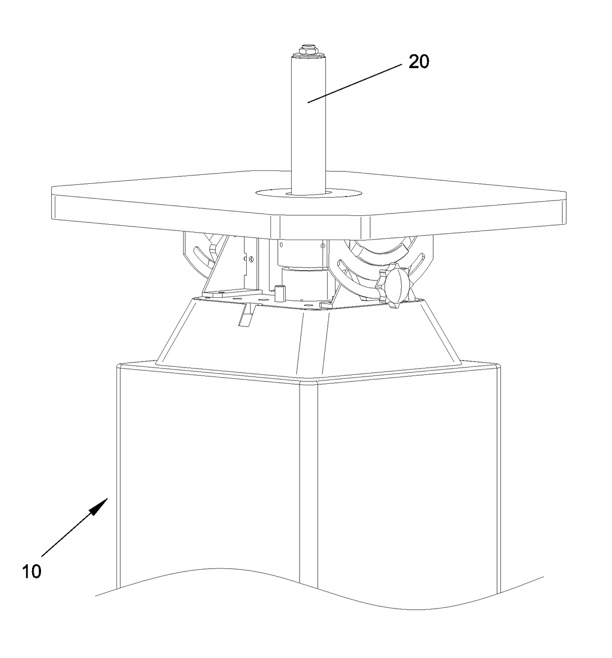
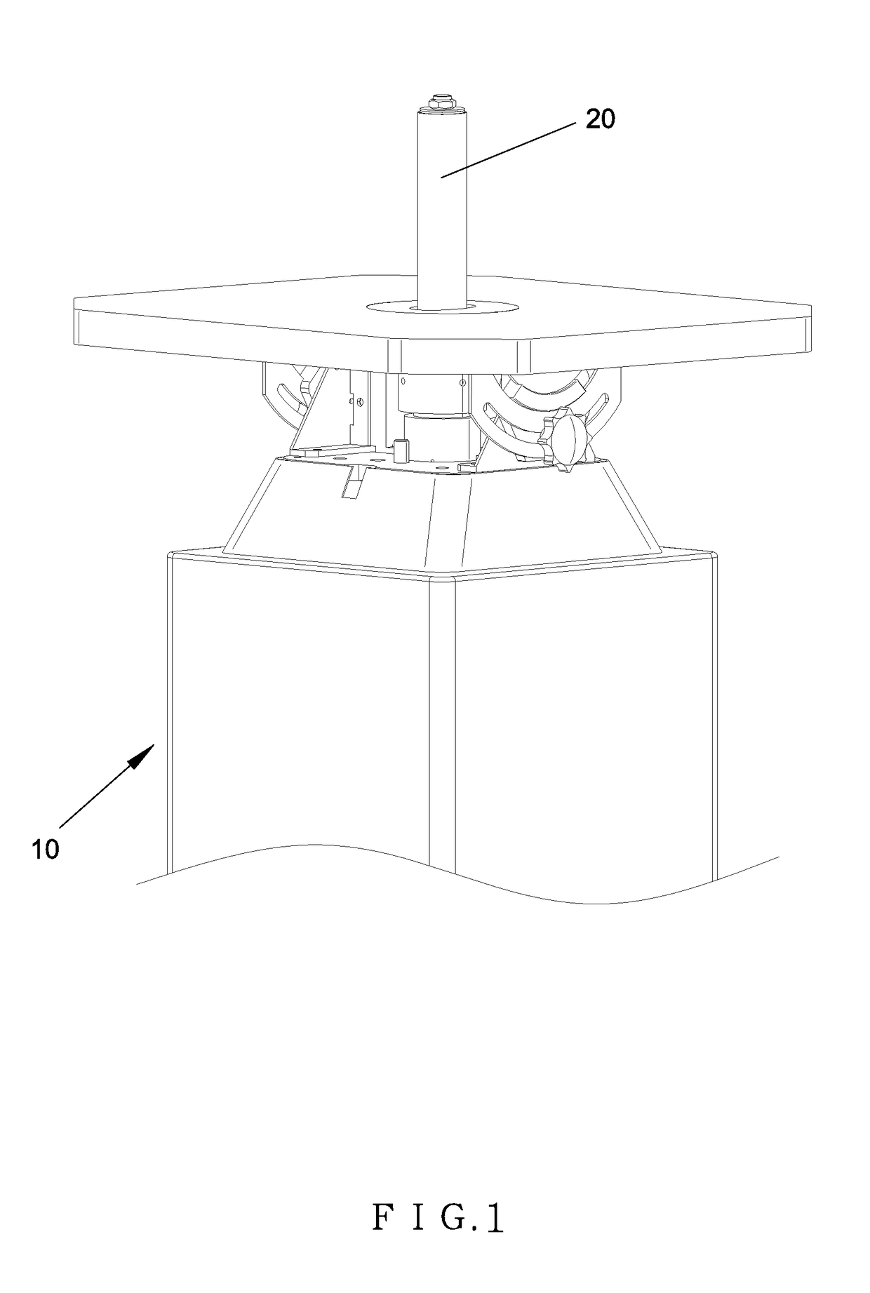
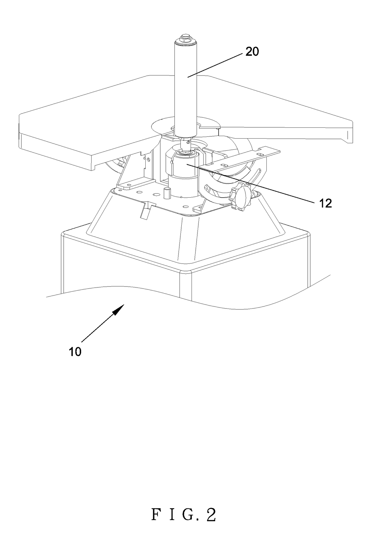
[0016]With reference to FIGS. 1 to 3, a removal structure for a central shaft of a sanding belt according to a preferred embodiment of the present invention is fixed on a grinding machine 10, and the grinding machine 10 comprises: a driver 11, a driving shaft 12 mounted on a top of the driver 11, a fitting sleeve 13 extending outwardly from a central position of the driving shaft 12, a conical groove 15 defined in the fitting sleeve 13, and at least one L-shaped notch 14 formed on a peripheral wall of the fitting sleeve 13 in an array arrangement. A connection column 20 is fitted with the driving shaft 12 and includes a central shaft 21 formed in a cone shape so as to correspond to the conical groove 15 of the fitting sleeve 13, wherein the central shaft 21 has at least one locking post 22, a number of which is equal to that of the at least one L-shaped notch 14.

[0017]Referring to FIGS. 3 to 5, the at least one locking post 22 of the central shaft 21 is inserted into the conical gro...


PUM


Abstract

A removal structure for a central shaft of a sanding belt is fixed on a grinding machine, and the grinding machine contains: a driver, a driving shaft mounted on a top of the driver, a fitting sleeve extending outwardly from a central position of the driving shaft, a conical groove defined in the fitting sleeve, and at least one L-shaped notch formed on a peripheral wall of the fitting sleeve. A connection column is fitted with the driving shaft and includes a central shaft formed in a cone shape so as to correspond to the conical groove of the fitting sleeve, and the central shaft has at least one locking post corresponding to the at least one L-shaped notch.

Description

FIELD OF THE INVENTION[0001]The present invention relates to a removal structure for a central shaft of a sanding belt which fixes a connection column with a grinding machine and removes the connection column from the grinding machine easily by using at least one L-shaped notch of the grinding machine and at least one locking post of the central shaft.BACKGROUND OF THE INVENTION[0002]A conventional grinding machine contains a central shaft of a sanding belt connected with its driving shaft by using at least one screw bolt, and the central shaft is removed from the driving shaft of the grinding machine by way of hand tools.[0003]For example, as removing the central shaft of the sanding belt, a first hand tool is used to fix a connection column, and a second hand tool is applied to screw or unscrew the at least one screw bolt, thus replacing the connection column troublesomely.[0004]The present invention has arisen to mitigate and / or obviate the afore-described disadvantages.SUMMARY O...

Claims


Application Information

Patent Timeline
IPC IPC(8): B24B41/04B24B21/00
CPCB24B21/00B24B41/04
Inventor WANG, LONG-WEI
Owner WANG LONG WEI
Why Eureka
Try Eureka