Winding structure of disc-type coreless permanent magnet motor and manufacturing method of winding structure

A winding structure, permanent magnet motor technology, applied in the shape/style/structure of winding conductors, windings, electric components, etc., can solve problems such as high efficiency, reduced slot fullness, and reduced motor performance

Active Publication Date: 2021-09-14
SHANGHAI DIANJI UNIV +1
View PDF15 Cites 1 Cited by
  • Summary
  • Abstract
  • Description
  • Claims
  • Application Information

AI Technical Summary

Problems solved by technology

[0005] The use of multi-strand thin electromagnetic round wires stranded or litz wires to make windings reduces eddy current loss to a certain extent and improves efficiency, but the slot fullness rate decreases, the volume of the motor and the amount of permanent magnets increase, and the power / torque density decreases; Windings made of copper wire or thin sheet copper have low eddy current loss, high efficiency, and high slot fill rate, but the insulation is easily damaged at the bending of the winding, especially at the end of the winding
According to the division of phase bands, multiple centralized independent coils are connected in series and parallel. There are many connecting lines between coils and coil groups, and the process is complicated. The size of the winding end is still large, the amount of materials is large, and the efficiency needs to be further improved.
Epoxy resin has low thermal conductivity, poor structural strength, and is easy to deform in high-temperature environments. The winding discs that rely on epoxy resin potting and positioning have poor mechanical strength and lack sufficient support. damage, affecting service life

Method used


Image

  • Winding structure of disc-type coreless permanent magnet motor and manufacturing method of winding structure
  • Winding structure of disc-type coreless permanent magnet motor and manufacturing method of winding structure
  • Winding structure of disc-type coreless permanent magnet motor and manufacturing method of winding structure

Examples


Embodiment Construction

[0041] The following will clearly and completely describe the technical solutions in the embodiments of the present invention with reference to the drawings in the embodiments of the present invention. Obviously, the described embodiments are part of the embodiments of the present invention, not all of them. Based on the embodiments of the present invention, all other embodiments obtained by persons of ordinary skill in the art without making creative efforts shall fall within the protection scope of the present invention.

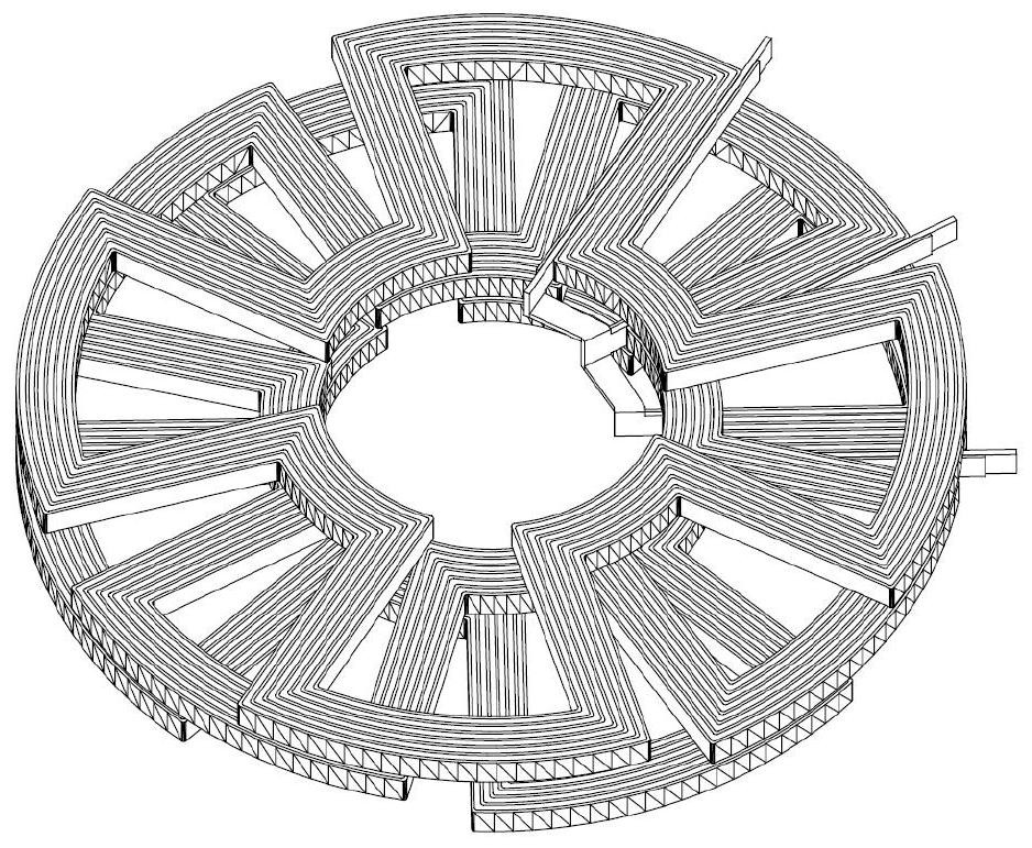
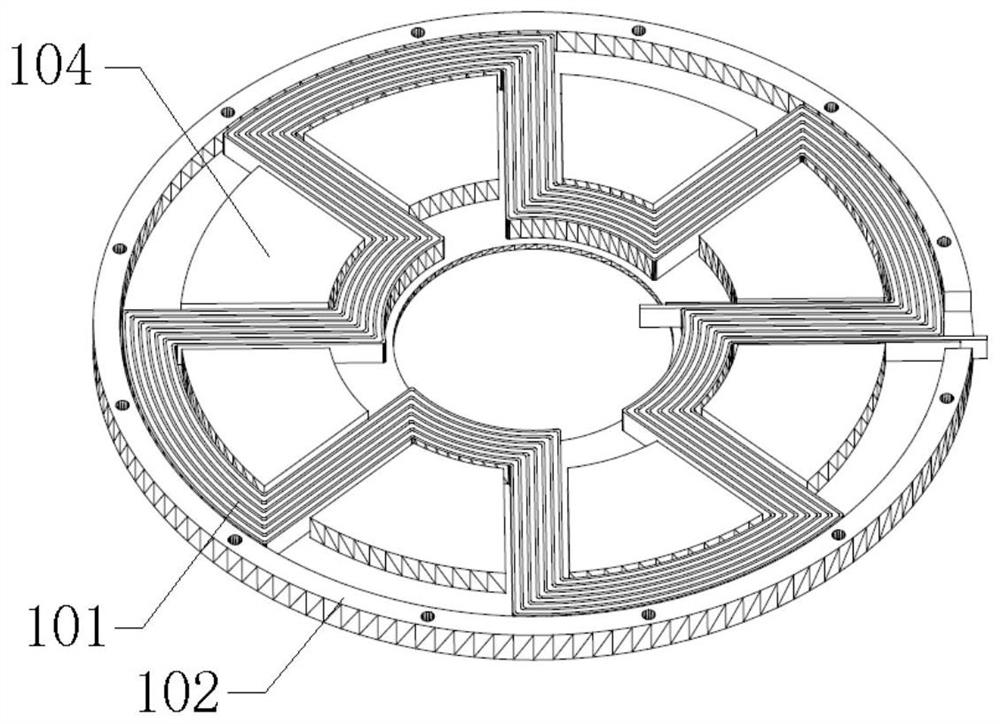
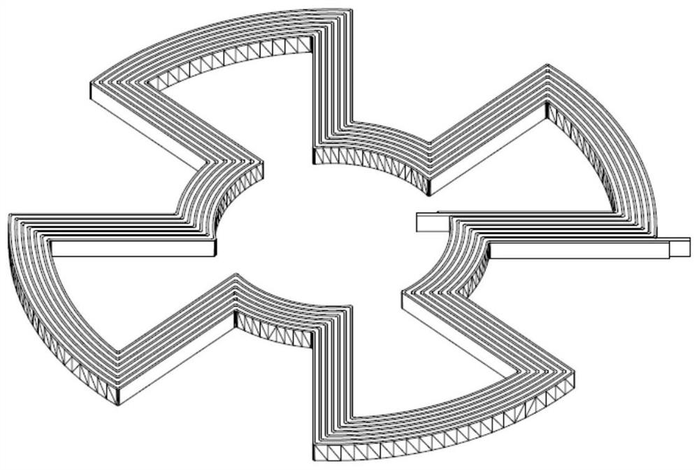
[0042] A winding structure of a disc-type ironless permanent magnet motor, the stacking method of the winding coils is as follows figure 1 As shown, its structure is as Figure 10 As shown, it includes three single-phase winding disks 1 and one side pressure plate 2. The single-phase winding disks 1 are stacked axially with an electrical angle of 120 degrees from each other in the circumferential direction. The three single-phase winding disks 1 are fixedl...


PUM


Abstract

The invention relates to a winding structure of a disc-type coreless permanent magnet motor and a manufacturing method of the winding structure, the winding structure comprises three single-phase winding discs and a side pressing plate, the single-phase winding discs are stacked in the axial direction in the circumferential direction with the difference of 120-degree electrical angles, the three single-phase winding discs are fixedly connected, and the side pressing plate is installed on the three-phase winding disc at the top. Compared with the prior art, the winding structure has the advantages of high production and operation efficiency, simple manufacturing process, material saving, low manufacturing cost, high mechanical strength, good heat dissipation and the like.

Description

technical field [0001] The invention relates to the technical field of ironless permanent magnet motor manufacturing, in particular to a winding structure of a disc-type ironless permanent magnet motor and a manufacturing method thereof. Background technique [0002] At present, the disc-type coreless permanent magnet motor has a series of advantages such as high power / torque density, high efficiency, low torque fluctuation, and stable operation. The propulsion device system has been rapidly popularized and applied. [0003] The existing disc-type coreless permanent magnet motor generally has surface-mounted permanent magnets on the circumference of the rotor. The permanent magnets use Halbach arrays to enhance the magnetic field in the motor and the sine degree of the air gap waveform. There is no iron core on the stator, only the winding and Non-magnetic, non-conductive insulating support material, so there is no torque ripple caused by cogging. There are two types of wi...

Claims


Application Information

Patent Timeline
Patent Type & Authority Applications(China)
IPC IPC(8): H02K3/04H02K3/28H02K3/47H02K15/04
CPCH02K3/04H02K3/28H02K3/47H02K15/0442H02K15/0464H02K2203/12
Inventor 王爱元姚晓东张海燕张超李子金
Owner SHANGHAI DIANJI UNIV
Why Eureka
Try Eureka