Method for improving ground

Inactive Publication Date: 2017-07-20
DAISHO CHEM R&D +1
View PDF0 Cites 1 Cited by
  • Summary
  • Abstract
  • Description
  • Claims
  • Application Information

AI Technical Summary

Benefits of technology

[0012]The method for improving ground of the present invention comprising the above steps can improve the strength(quality)of an underground consolidated body formed from a rich-mixed solidification material whose ratio of water to a cement (W/C) ranges from 26% to 40%, compared to the strength of an underground consolidated body formed with a conventional lean-mixed solidification material.
[0013]Herein, a solidification material (a rich-mixed solidification material whose W/C ranges from 26% to 40%) contains a high fluidity, and an increase in the viscosity of even a rich-mixed solidification material is reduced. Thus, the method for improving ground of the present invention can carry a rich-mixed solidification material by means of a pump for carrying a lean-mixed solidification material used in a prior art.
[0014]According to the present invention, if a partition forming material is injected prior to a step of cutting soil with a stable liquid, a separation layer (LD) composed of the partition forming material is formed between a lay

Problems solved by technology

However, a lower W/C might lead to more viscosity of a mixture of water and a cement, thereby blocking a carrying passage from a cement feed source to a jet device.
Thus, it is difficult to carry a solidification material to the jet device.
In addition, all of a solidification material injected from a jet device is not soli

Method used


Image

  • Method for improving ground
  • Method for improving ground
  • Method for improving ground

Examples


Embodiment Construction

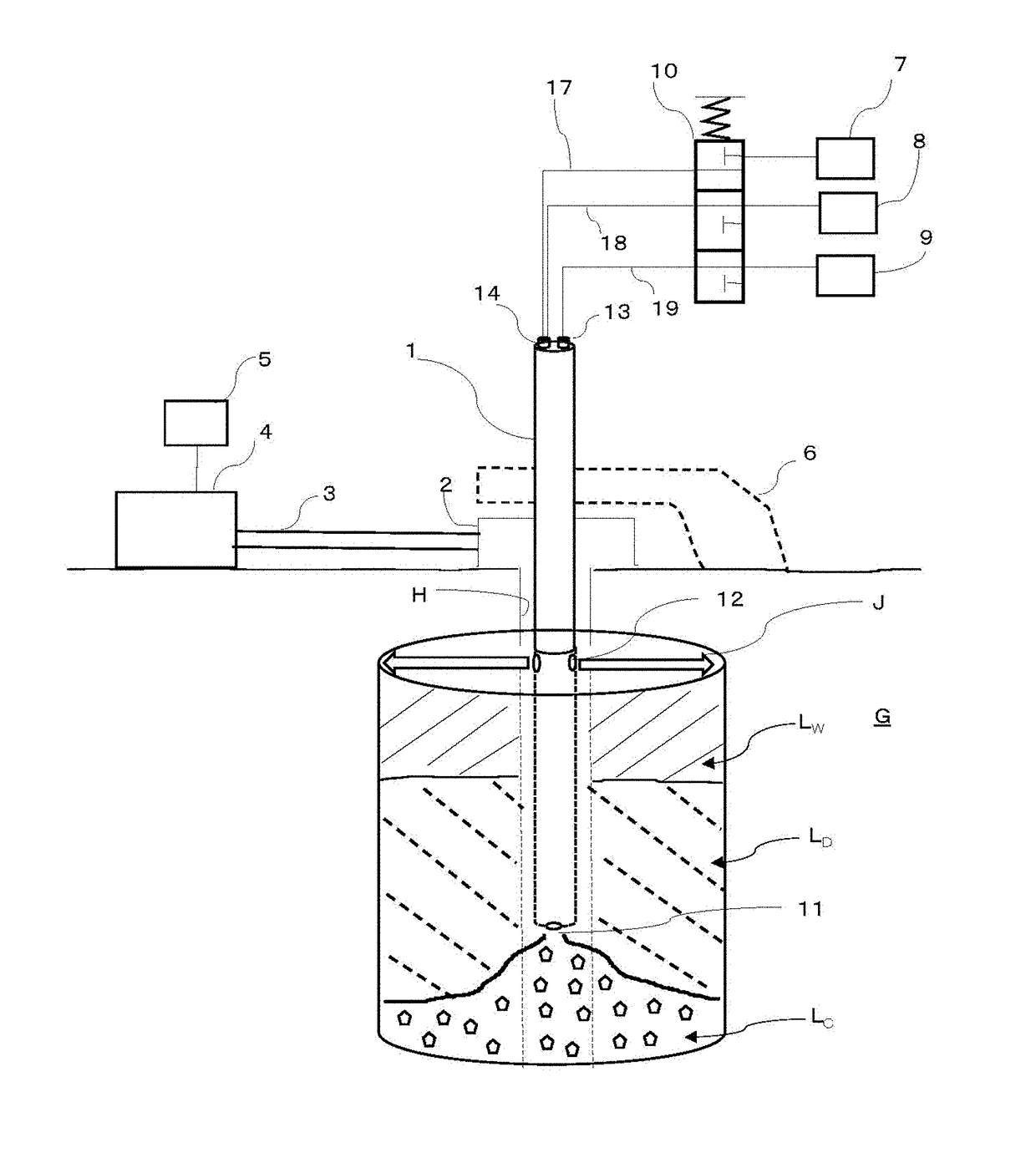
[0033]An embodiment of the present invention will be described with reference to the drawings.

[0034]First, an apparatus required for implementing an embodiment for the method for improving ground will be described with reference to FIG. 1.

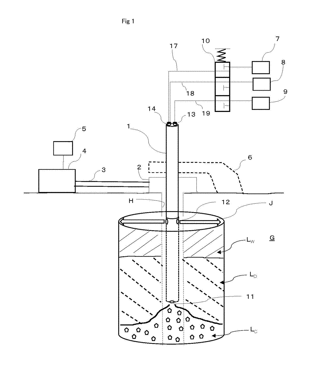
[0035]In FIG. 1, the ground to which the method for improving ground of the present invention is applied is denoted by a symbol G. A rod-shaped jet device 1 is inserted into a drilling hole H drilled in a ground G.

[0036]Herein, a installing mechanism 6 shown by dotted line in FIG. 1 is an apparatus for inserting (installing) the jet device 1 into the drilling hole H.

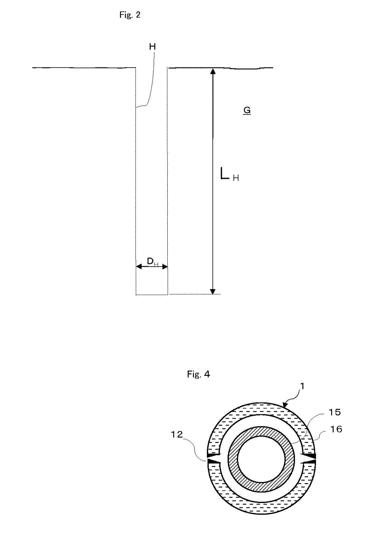
[0037]The jet device 1 is a double-pipe structure (FIG. 4, not shown in FIG. 1 in detail). In FIG. 4, an inner space of an inner pipe 15 provides a flow passage for feeding a rich-mixed solidification material. An annular space between the inner pipe 15 and an outer pipe 16 provides a flow passage for feeding as table liquid or a partition forming material.

[0038]In FIG. 1, a lower end p...


PUM


Abstract

A method for improving ground is capable of improving the strength or quality of an underground consolidated body formed by reducing the ratio of water to a “rich-mixed” solidification material (a cement) (W/C), assuredly carrying the solidification material from a feed source to a jet device, and reducing the amount of solidification material treated as an industrial waste in a construction process. The method for improving ground includes a step of drilling a drilling hole in the ground to be improved, a step of moving (pulling up) a jet device in a vertical direction by rotating the same while the jet device is inserted into the drilling hole and a fluid for cutting the ground (a stable liquid or a partition forming material) is injected from the jet device, and a step of injecting a solidification material from the jet device.

Description

TECHNICAL FIELD[0001]The present invention relates to a ground improvement technology that forms an underground consolidated body by cutting (in-situ) soil in the ground to be improved and mixing water and a solidification material such as cement and agitating a mixture thereof.BACKGROUND[0002]A technology for forming an underground consolidated body of a cylindrical shape by drilling a drilling hole in a ground to be improved, moving (pulling up or pushing down) a jet device in a vertical direction by rotating the same while the jet device is inserted into the drilling hole and a high-pressure fluid such as water is injected in an outward radial direction from the jet device to cut an in-situ soil, and by mixing the cut soil and a solidification material such as a cement and agitating a mixture thereof by injecting or delivering the solidification material to the soil has widely been known (e.g. Patent Document 1).[0003]In order to improve the strength (quality) of an underground c...

Claims


Application Information

Patent Timeline
IPC IPC(8): E02D3/12
CPCE02D3/12E02D2300/0023E02D2300/0018E02D2250/003
Inventor HANEDA, ATARU
Owner DAISHO CHEM R&D
Why Eureka
Try Eureka