Hydroelectric power generating system

a technology of hydroelectric power generation and hydroelectric power, which is applied in the direction of wind energy generation, mechanical equipment, machines/engines, etc., can solve problems such as net loss of energy, and achieve the effect of reducing sea level and “clean” energy

Active Publication Date: 2017-07-20
BARAKAT YASER
View PDF11 Cites 14 Cited by
  • Summary
  • Abstract
  • Description
  • Claims
  • Application Information

AI Technical Summary

Problems solved by technology

While this system results in a net loss of energy, it does enable the reservoir to be replenished during periods where surplus electrical energy is available.

Method used


Image

  • Hydroelectric power generating system
  • Hydroelectric power generating system
  • Hydroelectric power generating system

Examples


first embodiment

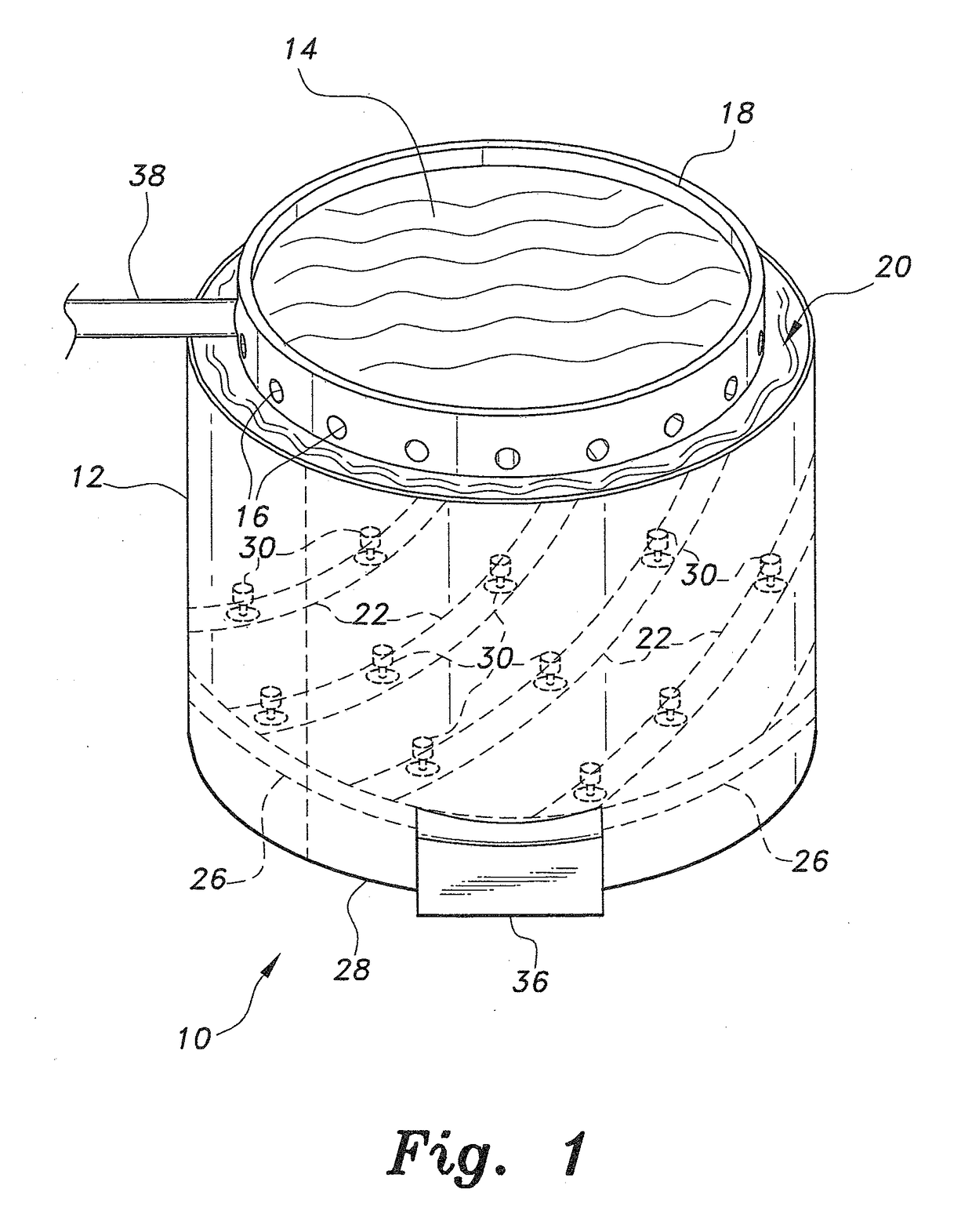
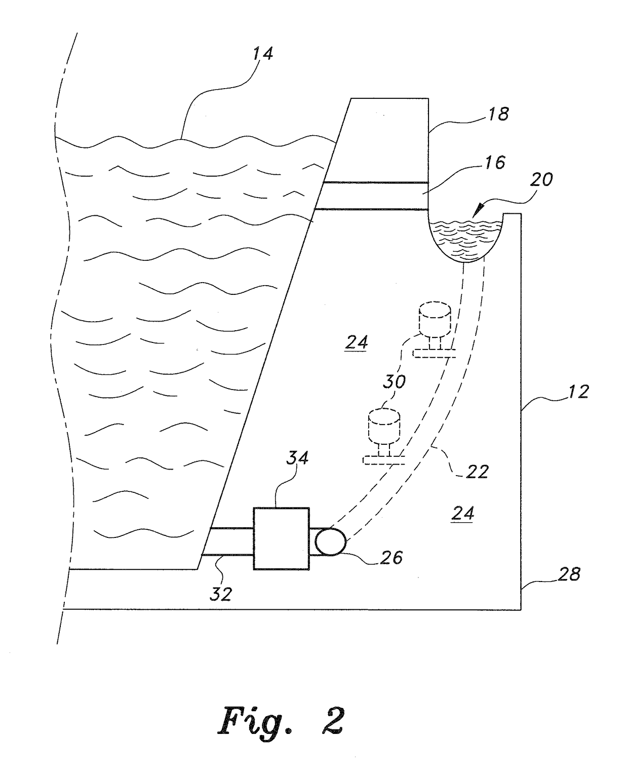
[0028]FIGS. 1-10B depict various embodiments of a hydroelectric power generating system according to the present teachings. Referring to FIGS. 1-2, a hydroelectric power generating system, generally designated as 10, is shown. The system 10 incorporates a relatively large dam 12 or wall defining a dam that completely encircles or laterally encloses a reservoir 14 therein. The dam 12 may have a generally cylindrical configuration, as shown in FIG. 1, or may have any other desired external shape or configuration. The dam 12 includes at least one sluice gate 16 (and preferably a plurality of sluice gates 16) extending through the upper portion 18 thereof. The sluice gates 16 permit the flow of water from the upper levels of the reservoir 14 through the dam 12 and into an externally disposed peripheral canal 20 that surrounds the upper portion 18 of the dam 12.

[0029]At least one penstock 22 (preferably a plurality of penstocks 22) extends from the peripheral canal 20 downward through th...

second embodiment

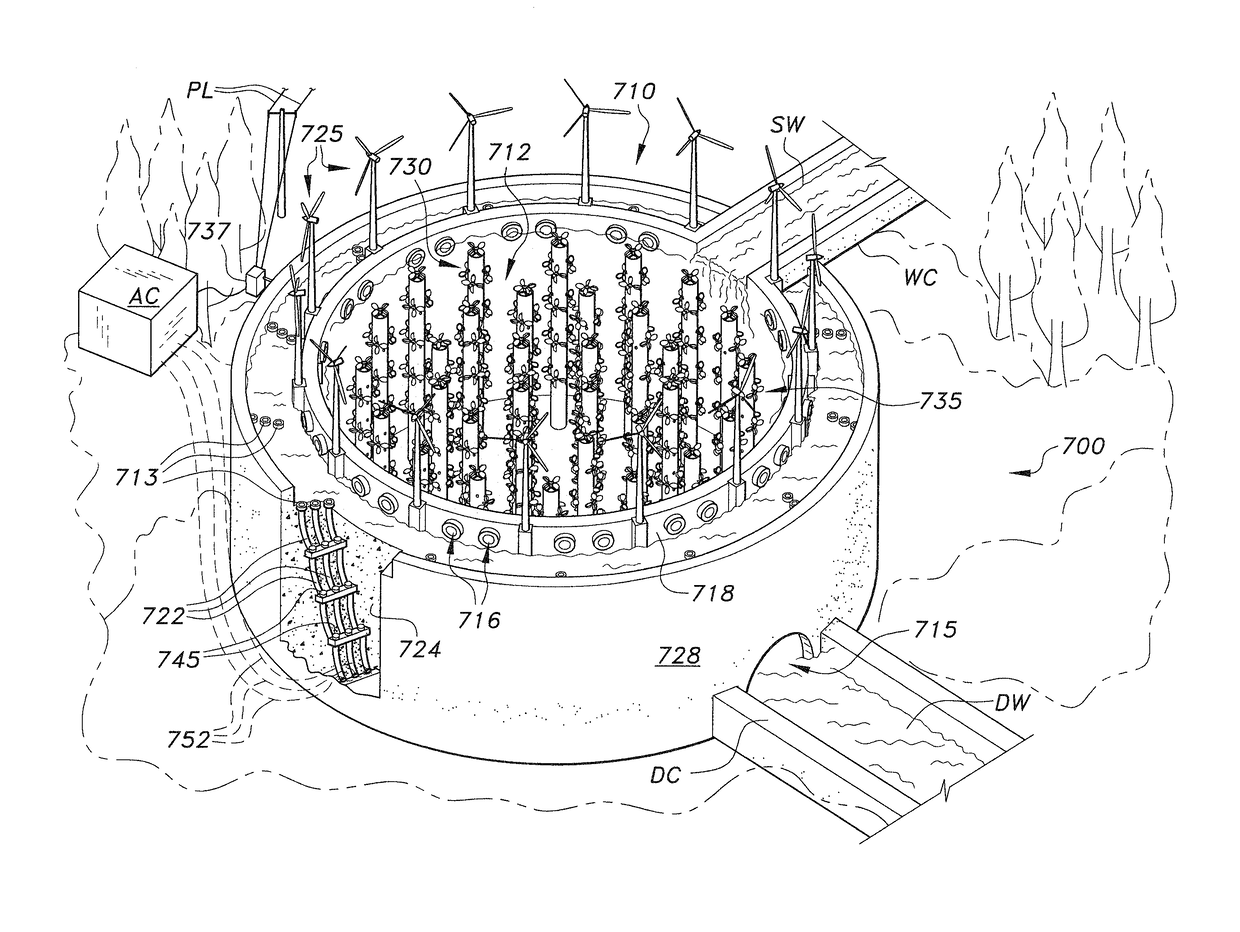
[0032]Referring to FIGS. 3-5, 6A, and 6B, a hydroelectric power generating system, generally designated as 110, is shown. The system 110 includes features that enhance the utilization of hydrodynamics to produce energy. Referring to FIG. 3 of the drawings, the hydroelectric power generating system 110 incorporates a relatively large dam 112 or wall defining a dam that completely encircles or laterally encloses a reservoir 114 therein, and an auxiliary power generating system 150 within said reservoir 114. The dam 112 can have a generally cylindrical configuration, as shown in FIG. 3, or may have any other desired external shape or configuration. The dam 112 includes at least one sluice gate 116 (and preferably a plurality of sluice gates 116) extending through the upper portion 118 thereof and an annular tunnel 140 within the interior 124 of the base 128 of the dam 112, as generally illustrated in FIG. 4 of the drawings. The sluice gates 116 permit the flow of water from the upper l...


PUM


Abstract

The hydroelectric power generating system includes a reservoir for retaining a body of water and an outer vessel that surrounds a peripheral wall of the reservoir. A circumferential canal extends between an upper portion of the reservoir peripheral wall and the outer vessel. One or more penstocks extend below the canal between the reservoir and the outer vessel. Each penstock has one or more hydroelectric turbine generators installed therealong. A plurality of primary wind turbines can be disposed on a peripheral wall of the reservoir and a plurality of air columns can be disposed within the reservoir to generate auxiliary power.

Description

CROSS-REFERENCE TO RELATED APPLICATION[0001]This application claims the benefit of U.S. Provisional Patent Application Ser. No. 62 / 278,621, filed Jan. 14, 2016.BACKGROUND OF THE INVENTION[0002]1. Field of the Invention[0003]The present invention relates to electrical power generating systems, and particularly to a hydroelectric power generating system including a man-made reservoir with one or more penstocks extending from a common waterway and one or more electrical generating turbines disposed along each of the penstocks.[0004]2. Description of the Related Art[0005]Hydroelectric power generating systems have been known for a considerable period of time. Conventional systems utilize a natural geographic basin, valley, or the like, and place a man-made dam across a channel in the natural terrain to create a reservoir upstream of the dam. The water is then made to flow through one or more power generating turbines in the dam (or in a powerhouse constructed with the dam), to generate ...

Claims


Application Information

Patent Timeline
Patent Type & Authority Applications(United States)
IPC IPC(8): F01D15/10F03D9/00F03D9/25F03D1/00
CPCF01D15/10F03D9/25F03D9/002F03D1/00F03B13/06F03B13/08F03D9/008F05B2210/18F05B2210/401F05B2240/40F05B2250/231Y02E10/20Y02E10/72Y02E60/16
Inventor BARAKAT, YASER K.
Owner BARAKAT YASER
Why Eureka
Try Eureka