Segmented fluid end

a fluid end and segmented technology, applied in the direction of positive displacement liquid engine, piston pump, borehole/well accessories, etc., can solve the problems of shortening the life of the pressure valve and spring, and dramatically increasing wear and tear

Active Publication Date: 2017-07-20
BARNETT JR W H
View PDF0 Cites 68 Cited by
  • Summary
  • Abstract
  • Description
  • Claims
  • Application Information

AI Technical Summary

Benefits of technology

[0060]A method of replacing a valve seat, valve seat or valve spring, in a pump is provided, the method comprising the steps of: providing a segmented fluid end comprising interchangeable plunger manifolds, intake heads, and pressure heads; selecting a head comprising the valve seat, valve seat or valve spring; removing the selected head; providing a replacement head comprising a valve seat, valve seat and valve spring; replacing the selected head with the replacement head.
[0061]A method of replacing an intake head or pressure head in a pump is provided, the method comprising the steps of: providing a segmented fluid end comprising interchangeable plunger manifolds, intake heads, and pressure heads; selecting a head; removing the selected head; providing a replacement head; replacing the selected head with the replacement head.
[0062]A method of replacing a plunger manifold in a pump is provided, the method comprising the steps of: providing a segmented fluid end comprising one or more interchangeable plunger manifolds; selecting a plunger manifold; removing the selected plunger manifold; providing a replacement plunger manifold; replacing the plunger manifold with the replacement plunger manifold.

Problems solved by technology

This one sided wear shortens the life of the pressure valve and spring.
This wear is dramatically more than the even-flow distributed around the intake valve.

Method used


Image

  • Segmented fluid end
  • Segmented fluid end
  • Segmented fluid end

Examples


Embodiment Construction

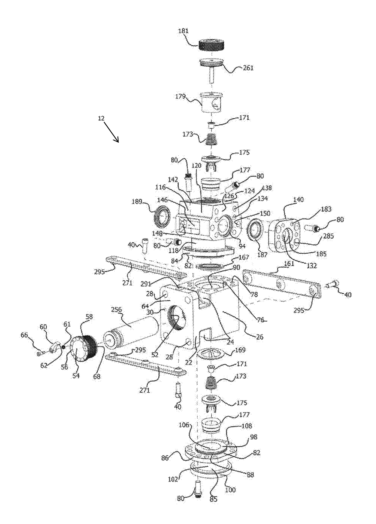
[0098]The present invention in its various embodiments and aspects of such embodiments provides a segmented fluid end which may be easily manufactured, repaired, or replaced. As used herein, the terms “a” or “an” shall mean one or more than one. The term “plurality” shall mean two or more than two. The term “another” is defined as a second or more. The terms “including” and / or “having” are open ended (e.g., comprising). The term “or” as used herein is to be interpreted as inclusive or meaning any one or any combination. Therefore, “A, B or C” means “any of the following: A; B; C; A and B; A and C; B and C; A, B and C”. An exception to this definition will occur only when a combination of elements, functions, steps or acts are in some way inherently mutually exclusive.

[0099]Reference throughout this document to “one embodiment,”“certain embodiments,”“an embodiment,” or similar term means that a particular feature, structure, or characteristic described in connection with the embodime...


PUM


Abstract

A segmented fluid end is provided, the fluid end comprising a plurality of fluid end segments, each comprising a plunger manifold, intake head, and pressure head. In preferred embodiments, the fluid end comprises three fluid end segments (“triplex”) or five fluid end segments (“quint”). The plunger manifold comprises first and second mounting surfaces, each comprising a fluid opening. An intake head mounting flange is adapted to be removably coupled to the first mounting surface and a pressure head mounting flange is adapted to be removably coupled to the second mounting surface. The plunger manifold comprises a plunger mounting member comprising a plunger opening adapted to receive a plunger. The pressure heads are adapted for cooperative coupling to adjacent pressure heads, such that, when coupled, the pressure heads are in fluid communication with one another. Methods of replacing the fluid end segments, plunger manifolds, pressure heads, and intake heads are provided.

Description

1. FIELD OF THE INVENTION[0001]This invention relates in general to fluid ends used in plunger type reciprocating pumps and, in particular, to a segmented fluid end.2. BACKGROUND OF THE INVENTION[0002]Hydraulic fracturing is the injection, under pressure, of water, sand, and / or other fluids within a well formation to induce fractures in a rock layer. Oil and gas drilling operators commonly use hydraulic fracturing, or “fracking” to release petroleum and natural gas well as other substances from the rock layer. The high pressure injection creates new channels in the rock which can increase the extraction rates and ultimate recovery of fossil fuels. A hydraulic fracturing pump or “frac pump” is used to pump water, sand, gravel, acids, proprietary liquids and concrete into the well formation. The solids pumped down the hole into the fractures keep the fractures from closing after the pressure is released. Operators generally attempt to pump as much volume as possible at or above the pr...

Claims


Application Information

Patent Timeline
Patent Type & Authority Applications(United States)
IPC IPC(8): F04B53/22F04B53/10F04B19/22F04B53/00
CPCF04B53/22F04B53/007E21B43/26F04B19/22F04B53/10F04B1/0452F04B1/053F04B9/045F04B47/00F04B53/1032F04B53/16
Inventor BARNETT, JR., W.H.
Owner BARNETT JR W H
Why Eureka
Try Eureka