Indented antenna array for transmitter to receiver isolation

a transmitter-to-receiver isolation and antenna array technology, applied in the field of full duplex antenna arrays, can solve the problems of limited isolation, limited polarization choices in the transmission and reception of waves, and non-reciprocity approach with circulators, and achieve high antenna isolation, enhance antenna isolation, and practical and simple

Active Publication Date: 2017-07-20
RGT UNIV OF CALIFORNIA
View PDF1 Cites 12 Cited by
  • Summary
  • Abstract
  • Description
  • Claims
  • Application Information

AI Technical Summary

Benefits of technology

[0011]The technology of this disclosure offers a new technique to realize high antenna isolations that can be directly applied to the new class of radio systems that are called full-duplex radio, which transmit and receive signal and information at the same frequency and the same time. The technology will offer a practical and simple way to enhance the antenna isolation while allowing the array being used for beamforming or gain enhancements.

Problems solved by technology

The polarization diversity approach also limits the choices of polarization in the transmission and reception of the waves.
The non-reciprocity approach with circulators can only offer limited isolation and it is ineffective to the leakage from the antenna reflection of the transmitted power.

Method used


Image

  • Indented antenna array for transmitter to receiver isolation
  • Indented antenna array for transmitter to receiver isolation
  • Indented antenna array for transmitter to receiver isolation

Examples


Embodiment Construction

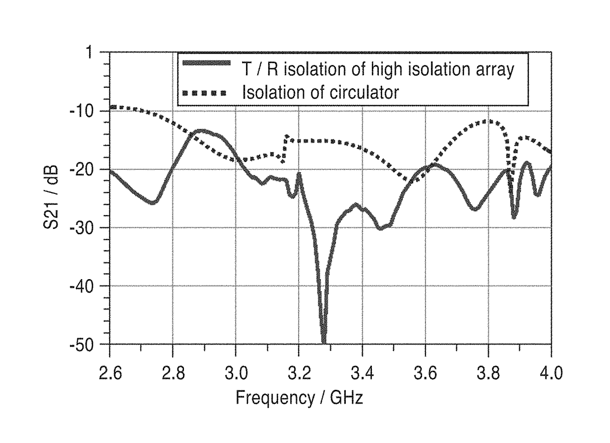
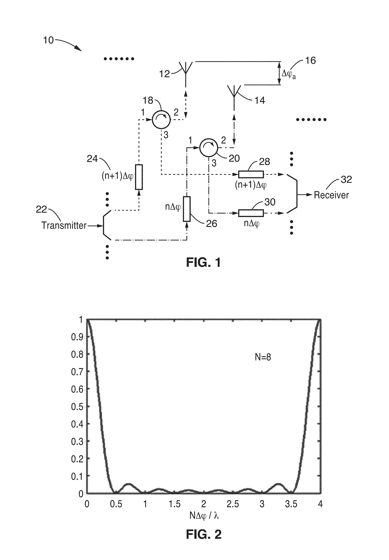
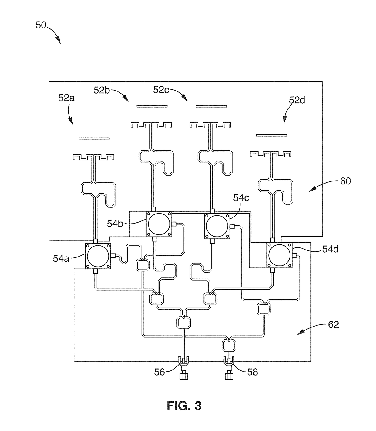
[0021]An antenna isolation enhancement technique is disclosed which is based on breaking spatial symmetry between transmitting / receiving (T / R) signal paths and the transmitter to receiver leakage path. Physically, this is accomplished by selectively indenting the antenna elements in an array from the conventional configuration of broadside alignments, preferably toward a specific tilted relationship. The different phase delay characteristics of the T / R paths in the disclosed indented antenna array improve the T / R isolation from what is offered by circulators while suppressing leakage due to antenna reflection and mutual coupling among antenna elements. The leakage power in this configuration is suppressed without limiting the choices of antenna polarizations and radiation patterns.

[0022]The approach behind the disclosed indented array is that when antenna elements are offset away from a broadside alignment, the transmitting or receiving waves travel a single trip through the indent,...


PUM


Abstract

An apparatus and method for enhancing full-duplex radio communications using an indented transmitter and receiver antenna. A multi-element antenna array is configured with each antenna coupled to a circulator that has connections to both a transmission path and a receiving path. The apparatus is configured with indentations that provide a tilting of the array from its broadside to create a progressive phase delay between adjacent pairs of elements. Transmitted and received waves travel a single trip through the indention, while antenna reflection or circulator leakage travels a round trip through indention, so that these signal components can be readily separated to achieve high levels of isolation during full-duplex transmitting and receiving.

Description

CROSS-REFERENCE TO RELATED APPLICATIONS[0001]This application claims priority to, and the benefit of, U.S. provisional patent application Ser. No. 62 / 280,982 filed on Jan. 20, 2016, incorporated herein by reference in its entirety.STATEMENT REGARDING FEDERALLY SPONSORED RESEARCH OR DEVELOPMENT[0002]Not ApplicableINCORPORATION-BY-REFERENCE OF COMPUTER PROGRAM APPENDIX[0003]Not ApplicableNOTICE OF MATERIAL SUBJECT TO COPYRIGHT PROTECTION[0004]A portion of the material in this patent document is subject to copyright protection under the copyright laws of the United States and of other countries. The owner of the copyright rights has no objection to the facsimile reproduction by anyone of the patent document or the patent disclosure, as it appears in the United States Patent and Trademark Office publicly available file or records, but otherwise reserves all copyright rights whatsoever. The copyright owner does not hereby waive any of its rights to have this patent document maintained in...

Claims


Application Information

Patent Timeline
Patent Type & Authority Applications(United States)
IPC IPC(8): H01Q3/32H04B1/44H01Q1/52H01Q21/00H01Q1/48H01Q1/50H04L5/14H01Q19/30
CPCH01Q3/32H04L5/1461H04B1/44H01Q1/523H01Q21/0075H01Q1/48H01Q1/50H01Q19/30H01Q1/525H04B1/525
Inventor WANG, YUANXUN ETHAN
Owner RGT UNIV OF CALIFORNIA
Why Eureka
Try Eureka