Integrated, closely spaced, high isolation, printed dipoles

a dipole and integrated technology, applied in the field of wireless communication, can solve the problems of multi-path or random coupling of in-band signal energy, common mode coupling and common mode coupling of radiated energy, and additional problems, so as to reduce electromagnetic coupling, increase antenna isolation, and reduce common mode current

Active Publication Date: 2006-11-23
QUALCOMM INC
View PDF4 Cites 97 Cited by
  • Summary
  • Abstract
  • Description
  • Claims
  • Application Information

AI Technical Summary

Benefits of technology

[0008] The present invention overcomes the above noted and other problems by providing an antenna configuration for a repeater in which two closely spaced antennas are orthogonally polarized to increase antenna isolation and reduce electromagnetic coupling. The two antennas may be fed in a balanced configuration to reduce common mode currents. The configuration is provided with a ground structure having various non-parallel and non-symmetrical shapes to reduce circulating currents and ground “hot spots” that can act as additional radiators thereby tending to increase coupling.
[0009] Alternatively, or in addition, to reducing shape symmetry and parallelism of the ground structure, an exemplary ground structure is provided with various printed structures that “choke” circulating ground currents by inducing opposite polarity currents that will generate electromagnetic (EM) fields with opposite, and thus canceling, polarities. The configuration may also be rotatable and capable of transmitting a sounding signal. By receiving the sounding signal during antenna rotation, the configuration is provided with feedback, which can be output to a user in the form of, for example, a sounding signal strength indicator or the like, providing information regarding antenna signal reflections to enable the user to directionally or spatially reposition the antenna configuration to maximize antenna operation.

Problems solved by technology

Three key problems present themselves when attempting to achieve high isolation between multiple, closely-spaced antennas that are printed on a small PCB board with near omni-directional antenna patterns and that must work in close proximity to unknown structures such as walls, furniture, and the like.
The problems are coupling of radiated energy, common mode coupling and multi-path or random coupling of in-band signal energy.
Additional problems can arise when attempting to maintain an omni or semi-omni directional antenna pattern.
Dealing with the second problem of common mode coupling involves a coupling mechanism that is difficult to cancel.
The problem of common mode coupling is especially difficult when multiple antennas are integrated together on a very small ground plane.
The third problem of random coupling is often the most difficult coupling mechanism to address.
However, attempting to determine an exact antenna placement that reduces or removes the unwanted components while preserving the desired components and the directionality is not generally successful.

Method used


Image

  • Integrated, closely spaced, high isolation, printed dipoles
  • Integrated, closely spaced, high isolation, printed dipoles
  • Integrated, closely spaced, high isolation, printed dipoles

Examples


Embodiment Construction

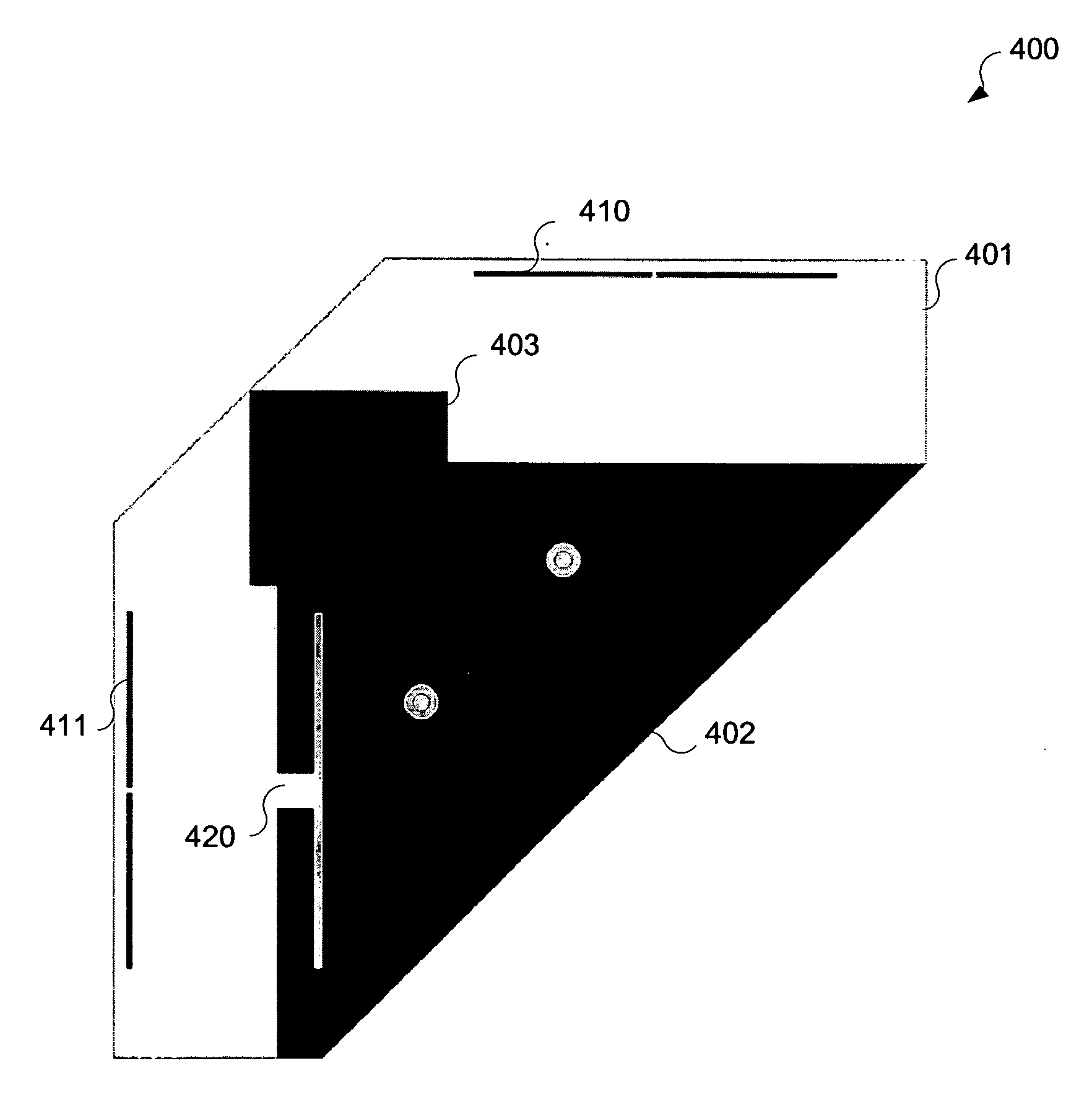
[0020] Referring now to the drawings in which like numerals reference like parts, several exemplary embodiments in accordance with the present invention will now be described. To address the above noted problems and other problems, an exemplary antenna configuration is provided where printed dipoles, or dipole elements, are positioned so as to be orthogonally polarized. The interference cause by a signal emanating from one radiating antenna into the adjacent antenna can be cancelled by establishing a polarity or orientation of the adjacent antenna having a natural tendency to cancel the signal energy which is produced with an electromagnetically opposite polarity or orientation from the radiating antenna.

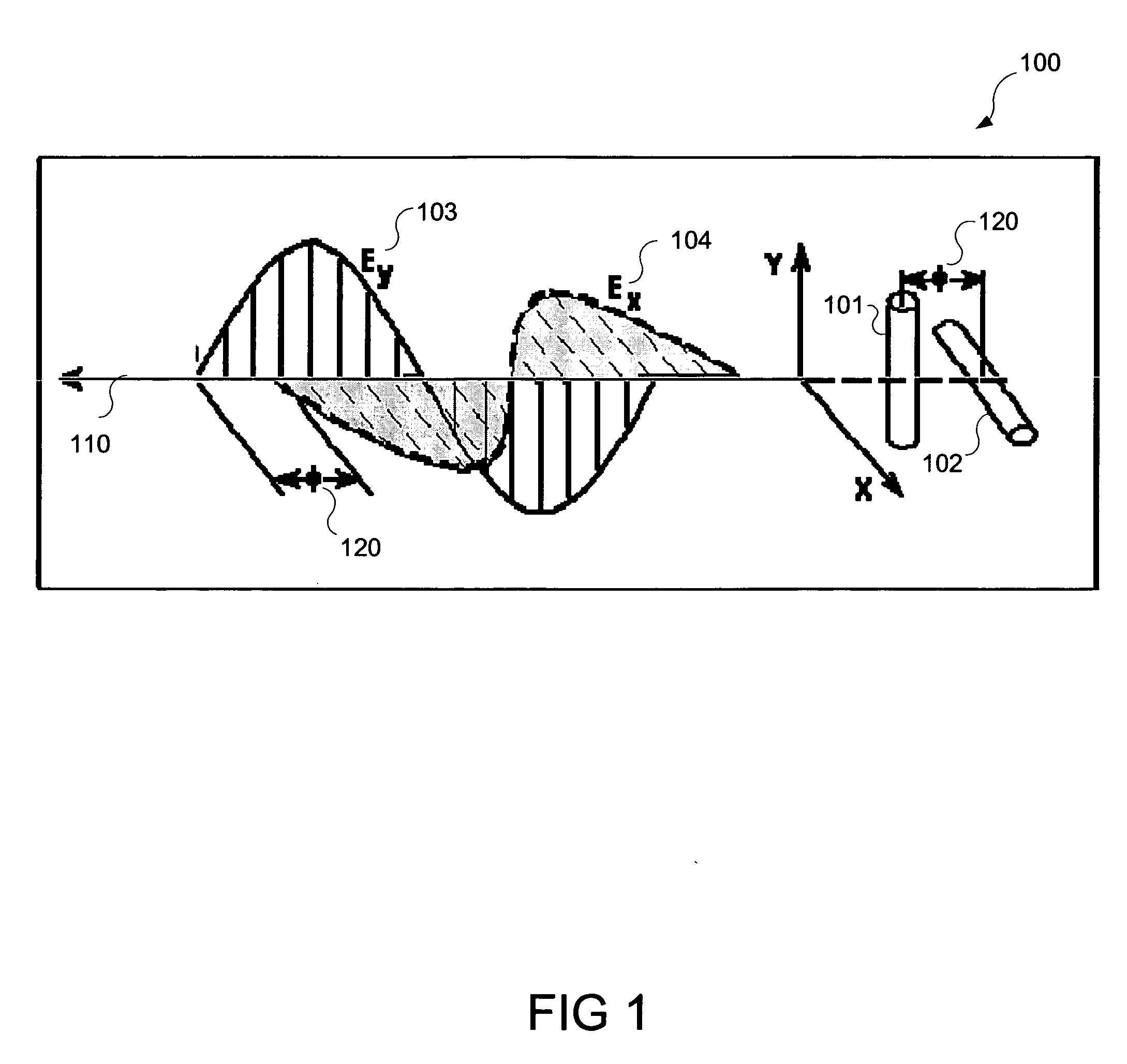
[0021] It will be appreciated that the polarization of an antenna relates to the orientation of an electric field of a propagating signal radiated from the antenna and can be determined by the physical structure of the antenna and by its orientation. In contrast, the directionality...


PUM


Abstract

An antenna configuration includes two closely spaced antennas each positioned so as to be orthogonally polarized with respect to the other. The antenna configuration increases antenna isolation and reduces electromagnetic coupling between donor side antenna and repeat side antenna. The antennas include printed dipoles connected to respective transceivers through respective baluns to balance the non-symmetrical portions of the antenna feed paths to reduce unwanted radiation therein. Printed features such as chokes and non-symmetrical and non-parallel structures are preferably included in the ground plane of a multi-layer circuit board to reduce or eliminate circulating ground currents.

Description

CROSS REFERENCE TO RELATED APPLICATIONS [0001] The present invention is related to and claims priority from U.S. Provisional Application No. 60 / 681,948, entitled “INTEGRATED, CLOSELY SPACED, HIGH ISOLATION, PRINTED DIPOLES,” filed May 18, 2005, the contents of which are incorporated herein by reference.FIELD OF THE INVENTION [0002] The present invention relates generally to wireless communications and more specifically to closely spaced antennas utilizing orthogonal polarization to reduce electromagnetic coupling. BACKGROUND OF THE INVENTION [0003] In certain circumstances, it becomes necessary to closely position multiple omni directional antennas, such as those used in repeaters, where the antennas for both the donor and subscriber sides of the repeater are placed in close proximity. For example, such closely spaced antennas can be embedded onto low cost printed circuit boards for use in various communications products and systems, such as in the WiDeFi™ TDD based repeater system....

Claims


Application Information

Patent Timeline
Patent Type & Authority Applications(United States)
IPC IPC(8): H01Q9/28
CPCH01Q9/285
Inventor GAINEY, KENNETH M.SNYDER, CHRISTOPHER A.PROCTOR, JAMES A. JR.
Owner QUALCOMM INC
Why Eureka
Try Eureka