Radio-Frequency Device and Wireless Communication Device for Enhancing Antenna Isolation

a radio frequency device and antenna isolation technology, applied in the direction of antennas, antenna details, basic electric elements, etc., can solve the problems of not meeting the broadband requirement of wireless communication systems, the radiation elements of such antennas are too long to be installed in miniature wireless communication systems, etc., to achieve enhanced isolation, enhanced antenna isolation, and improved antenna efficiency and bandwidth.

Active Publication Date: 2016-10-06
WISTRON NEWEB
View PDF6 Cites 9 Cited by
  • Summary
  • Abstract
  • Description
  • Claims
  • Application Information

AI Technical Summary

Benefits of technology

[0008]An objective of the present invention is to provide a radio-frequency device and wireless communication device capable of enhancing antenna isolation so as to dispose multiple sets of antennas in a limited space while maintaining preferable antenna efficiency and bandwidth.
[0009]An embodiment of the present invention discloses a radio-frequency device for a wireless communication device. The radio-frequency device includes an antenna disposition area, a grounding element, a first antenna, a second antenna, a third antenna and a second parasitic element. The first antenna is disposed in the antenna disposition area for transmitting or receiving a first radio signal, wherein the first antenna includes a metal coupling piece; a first radiating element, electrically connected to the grounding element for emitting the first radio signal; a first signal feed-in element, electrically connected to the metal coupling piece for coupling the first radio signal to the first radiating element via the metal coupling piece such that the first radio signal is emitted via the first radiating element; and a first parasitic element, electrically connected to the grounding element. The second antenna is disposed in the antenna disposition area for transmitting or receiving a second radio signal. The third antenna is disposed in the antenna disposition area for transmitting or receiving a third radio signal. The second parasitic element is disposed in the antenna disposition area and is electrically connected to the grounding element for guiding a first reflected signal generated from the first radio signal to the second parasitic element so as to enhance isolations of the first antenna, the second antenna and the third antenna. The grounding element between the first antenna, the second parasitic element, the second antenna and the third antenna is shared by the first antenna, the second antenna and the third antenna. The metal coupling piece is disposed between the first parasitic element and the first radiating element. The first parasitic element is used for guiding a second reflected signal generated from the second radio signal and a third reflected signal generated from the third radio signal to the first parasitic element so as to enhance isolations of the first antenna, the second antenna and the third antenna.
[0010]Another embodiment of the present invention discloses a wireless communication system including a system grounding element, for providing ground; a radio signal processing unit, for processing a plurality of radio signals; and a radio-frequency device. The radio-frequency device includes an antenna disposition area, a grounding element, a first antenna, a second antenna, a third antenna and a second parasitic element. The first antenna is disposed in the antenna disposition area for transmitting or receiving a first radio signal of the plurality of radio signals, wherein the first antenna includes a metal coupling piece; a first radiating element, electrically connected to the grounding element for emitting the first radio signal; a first signal feed-in element, electrically connected to the metal coupling piece for transmitting the first radio signal to the first radiating element via the metal coupling piece such that the first radio signal is emitted via the first radiating element; and a first parasitic element, electrically connected to the grounding element. The second antenna is disposed in the antenna disposition area for transmitting or receiving a second radio signal of the plurality of radio signals. The third antenna is disposed in the antenna disposition area for transmitting or receiving a third radio signal of the plurality of radio signals. The second parasitic element is disposed in the antenna disposition area and is electrically connected to the grounding element for guiding a first reflected signal generated from the first radio signal to the second parasitic element so as to enhance isolations of the first antenna, the second antenna and the third antenna. The grounding element between the first antenna, the second parasitic element, the second antenna and the third antenna is shared by the first antenna, the second antenna and the third antenna. The metal coupling piece is disposed between the first parasitic element and the first radiating element. The first parasitic element is used for guiding a second reflected signal generated from the second radio signal and a third reflected signal generated from the third radio signal to the first parasitic element so as to enhance isolations of the first antenna, the second antenna and the third antenna.

Problems solved by technology

However, if the overall size of the wireless communication device or the available space for disposing the antennas is very small, careful considerations must be taken when drawing the layout of the antennas.
The common broadband antennas, such as planar inverted-F antennas, can meet the requirement of multi-frequency operation; however, the radiation elements of such antennas are too long to be installed in a miniature wireless communication system.
Furthermore, the low frequency band of these kinds of antennas is too narrow (only about 110 MHz) so that they cannot meet the broadband requirement of the wireless communication systems.

Method used


Image

  • Radio-Frequency Device and Wireless Communication Device for Enhancing Antenna Isolation
  • Radio-Frequency Device and Wireless Communication Device for Enhancing Antenna Isolation
  • Radio-Frequency Device and Wireless Communication Device for Enhancing Antenna Isolation

Examples


Embodiment Construction

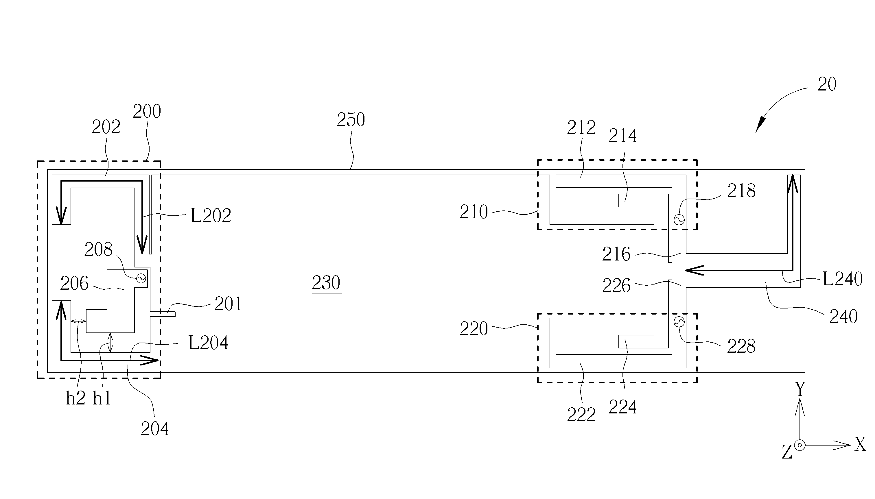
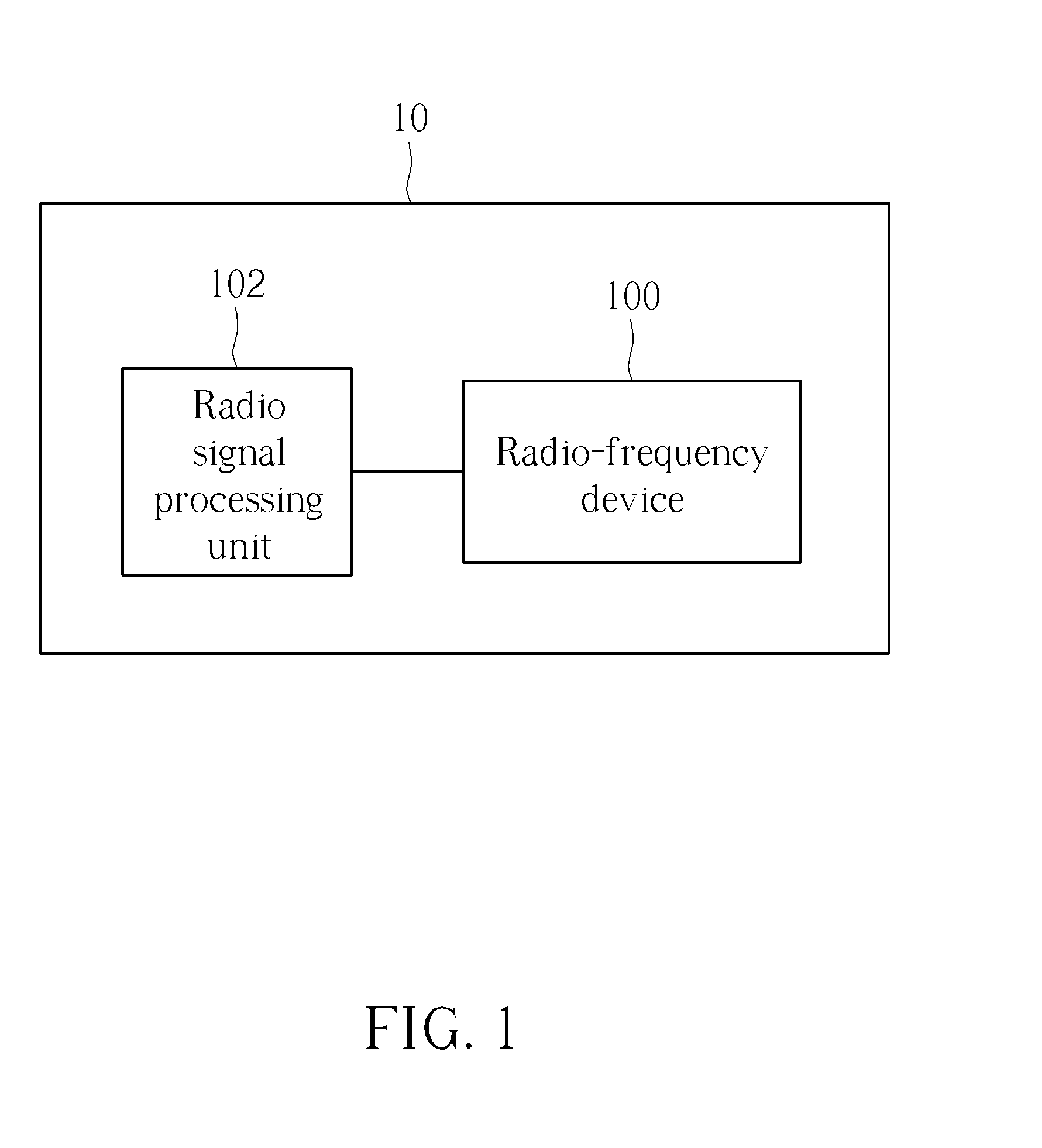
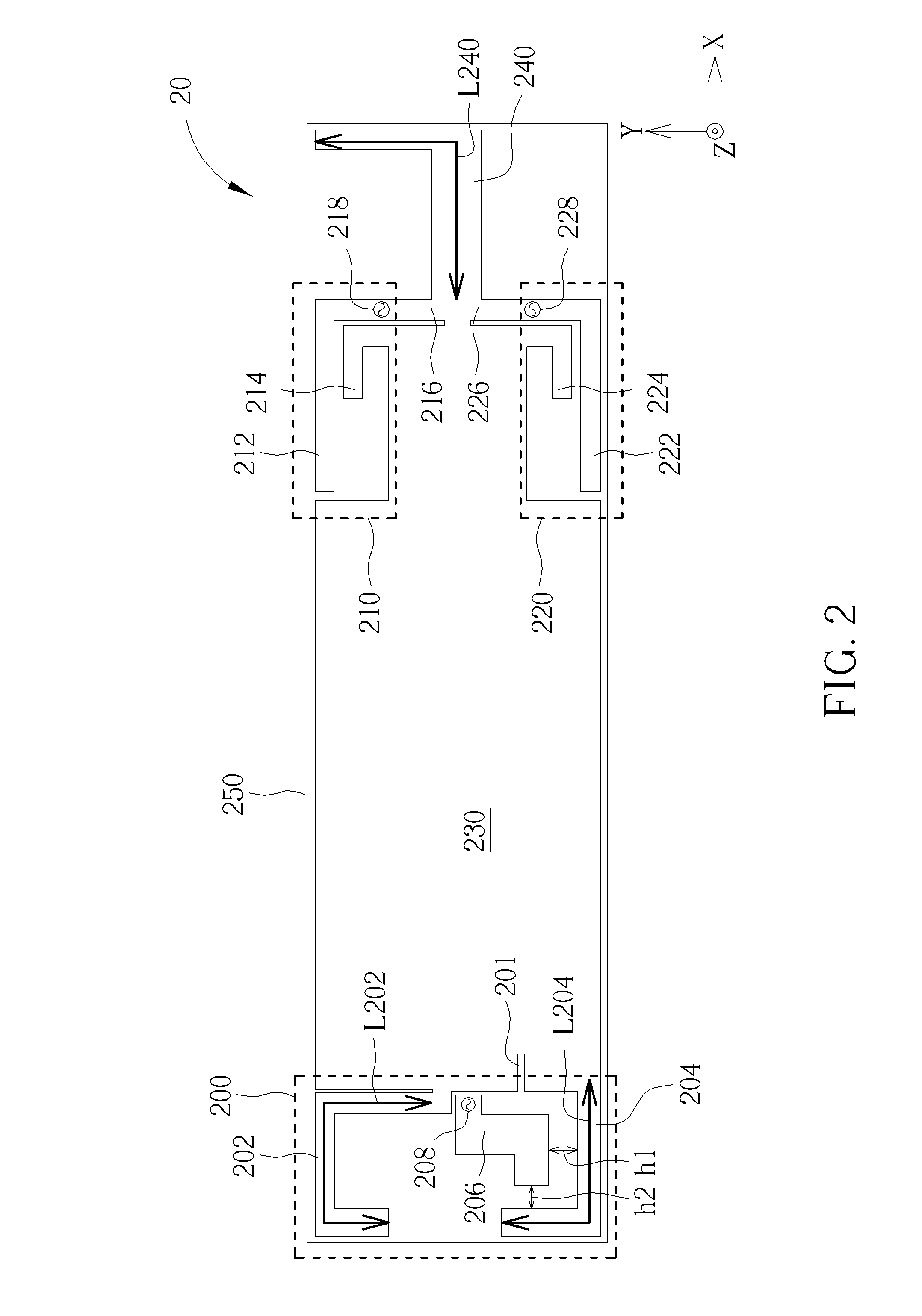
[0024]Please refer to FIG. 1, which is a schematic diagram of a wireless communication device 10 according to an embodiment of the present invention. The wireless communication device 10 may be any electronic product with wireless communication functionalities such as a mobile phone, a computer system, a wireless access point device, a wireless base station, a USB dongle, and so on. The wireless communication device 10 is briefly composed of a radio-frequency device 100 and a radio signal processing unit 102, but is not limited herein. The radio-frequency device 100 provides a wireless communication functionality of the wireless communication device 10. Specifically, the radio signal processing unit 102 may support an operation of simultaneous transmission or reception of wireless signals in the same frequency band, and the radio-frequency device 100 ensures isolation under this operation. Examples of “simultaneous transmission or reception of wireless signals in the same frequency ...


PUM


Abstract

A radio-frequency device includes a grounding element, a first antenna including a first parasitic element, a second antenna, a third antenna and a second parasitic element, wherein the grounding element is shared by the first, second and third antennas, the second parasitic element is electrically connected to the grounding element for guiding a first reflected signal from the first antenna to the second parasitic element, and the first parasitic element is electrically connected to the grounding element for guiding a second and third reflected signals from the second and third antennas to the first parasitic element, so as to enhance isolations of the first, second and third antennas.

Description

BACKGROUND OF THE INVENTION[0001]1. Field of the Invention[0002]The present invention relates to a radio-frequency device and wireless communication device, and more particularly, to a radio-frequency device and wireless communication device capable of enhancing antenna isolation so as to dispose multiple antennas in a limited space while maintaining preferable antenna efficiency and bandwidth.[0003]2. Description of the Prior Art[0004]Electronic products with wireless communication functionalities, such as laptops, tablet PCs, personal digital assistants (PDAs), mobile phones, wireless base stations, smart meters, and USB dongles, utilize antennas to send and receive wireless signals so as to access wireless networks. In order to let the users access wireless communication networks more conveniently, the antenna bandwidth should be as broad as possible so that more communication protocols can be complied with, while the antenna size should be minimized to meet a demand for smaller ...

Claims


Application Information

Patent Timeline
Patent Type & Authority Applications(United States)
IPC IPC(8): H01Q1/38H01Q9/04
CPCH01Q9/0407H01Q1/38H01Q1/243H01Q1/521H01Q5/378H01Q9/42
Inventor HSIEH, CHIA-HSING
Owner WISTRON NEWEB
Why Eureka
Try Eureka