Dualband antenna with isolation enhanced and method thereof

a dual-band antenna and enhanced technology, applied in the direction of elongated active element feed, resonant antenna, radiating element structure, etc., can solve the problems of signal interference between different antenna systems, signal interference is particularly severe, and the radiation efficiency is reduced, so as to improve the isolation effect of the antenna

Active Publication Date: 2016-06-30
REALTEK SEMICON CORP
View PDF4 Cites 10 Cited by
  • Summary
  • Abstract
  • Description
  • Claims
  • Application Information

AI Technical Summary

Benefits of technology

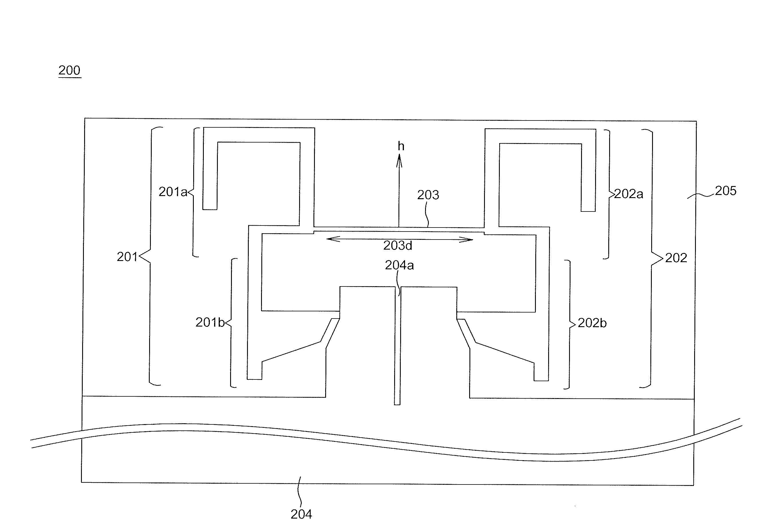
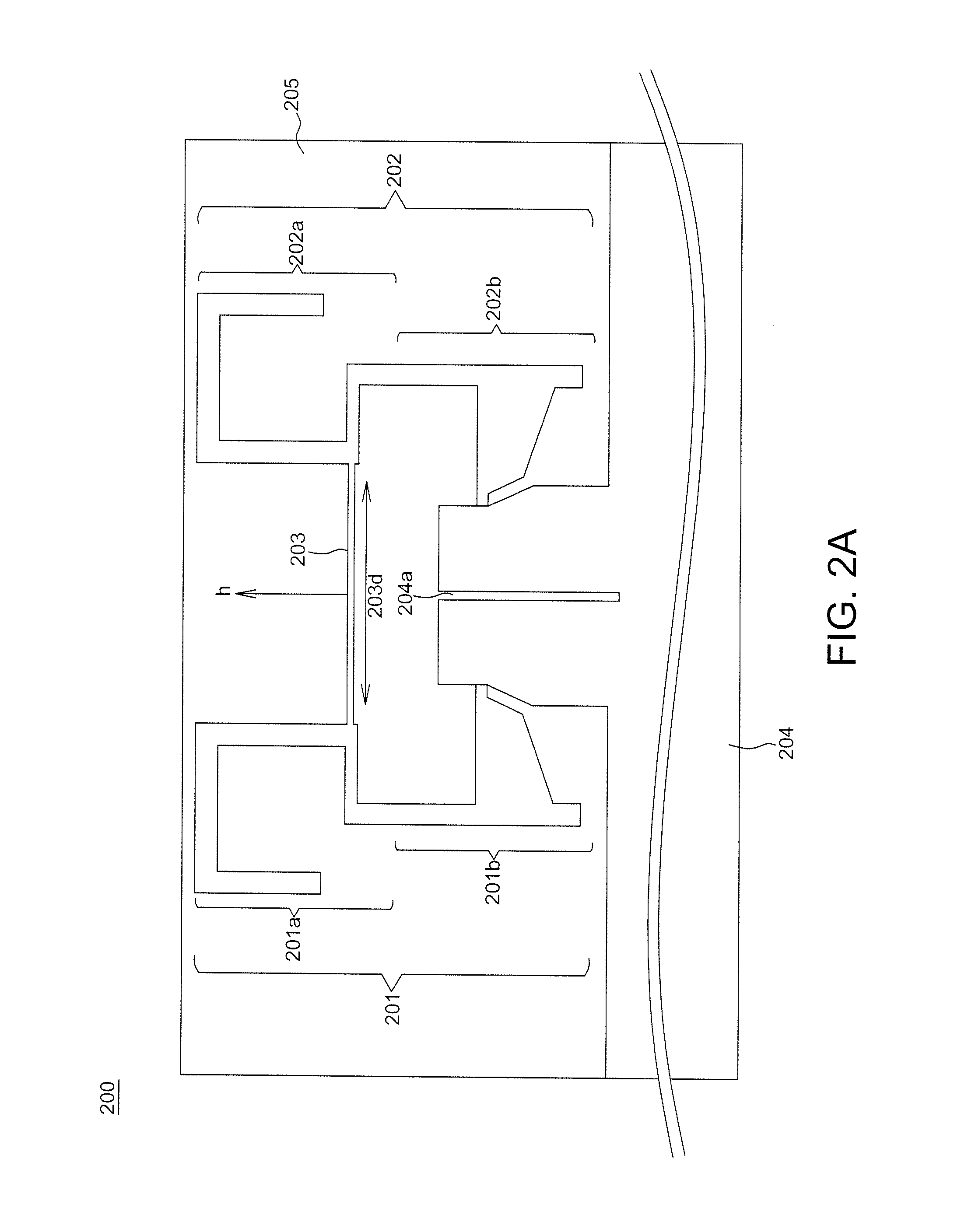
[0010]An object of the invention is to provide a dual-band antenna set for a multiple entry / exit system. The dual-band antenna set has a neutralized line and / or a slot used to enhance antenna isolation.

Problems solved by technology

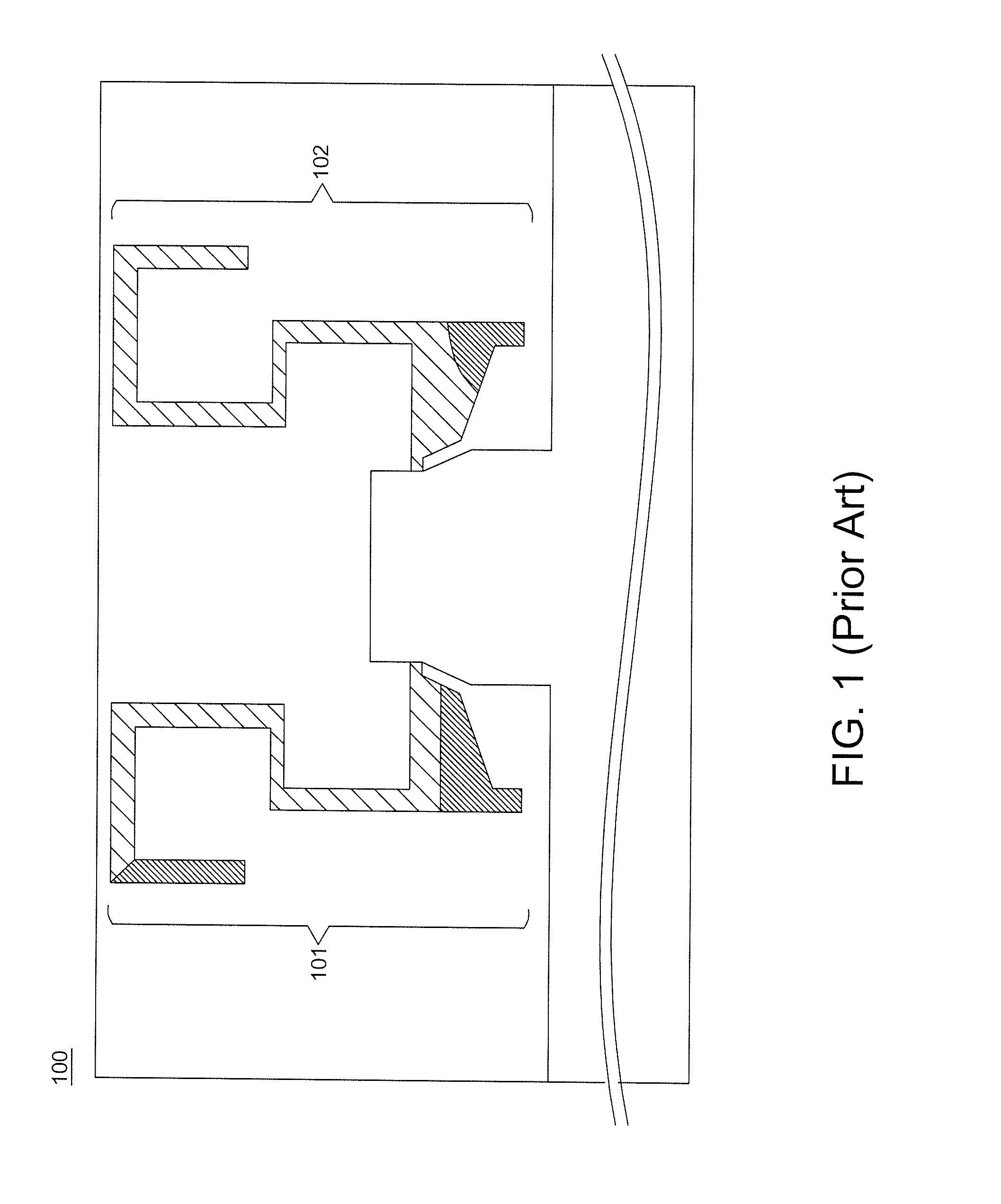
Because significant progress has been made on multiple entry / exit systems and integrated access devices, the number of antennas provided for a single apparatus is increased by several times to result in antenna coupling effects and thus reduce radiation efficiency.
Besides, signal interference among different antenna systems may occur, and the signal interference is particularly severe when different antenna systems operate in an identical frequency band.

Method used


Image

  • Dualband  antenna  with  isolation  enhanced and method  thereof
  • Dualband  antenna  with  isolation  enhanced and method  thereof
  • Dualband  antenna  with  isolation  enhanced and method  thereof

Examples


Embodiment Construction

[0024]In the following detailed description of the preferred embodiments, reference is made to the accompanying drawings which form a part hereof, and in which are shown by way of illustration specific embodiments in which the invention may be practiced. In this regard, directional terminology, such as “top,”“bottom,”“front,”“back,” etc., is used with reference to the orientation of the Figure(s) being described. The components of the present invention can be positioned in a number of different orientations. As such, the directional terminology is used for purposes of illustration and is in no way limiting. On the other hand, the drawings are only schematic and the sizes of components may be exaggerated for clarity. It is to be understood that other embodiments may be utilized and structural changes may be made without departing from the scope of the present invention. Also, it is to be understood that the phraseology and terminology used herein are for the purpose of description an...


PUM


Abstract

An antenna set includes a first antenna, a second antenna, and a neutralized line. Each of the first antenna and the second antenna has a low frequency resonant path and a high frequency resonant path. The neutralized line is couple to the low frequency resonant path of the first antenna and the low frequency resonant path of the second antenna. The low frequency resonant path of the first antenna and the low frequency resonant path of the second antenna correspond to a first frequency band, the high frequency resonant path of the first antenna and the high frequency resonant path of the second antenna correspond to a second frequency band, and the two low frequency resonant paths do not overlap the two high frequency resonant paths.

Description

[0001]This application claims the benefit of the filing date of Taiwan Application Ser. No. 103145730, filed on Dec. 26, 2014, the content of which is incorporated herein by reference.BACKGROUND OF THE INVENTION[0002]a. Field of the Invention[0003]The invention relates to an antenna set and an isolation enhancement method for use with different systems having dual-band antennas, where the dual-band antennas achieve high isolation when the different systems operate in an identical frequency band.[0004]b. Description of the Related Art[0005]An antenna is a key component for wireless communications systems. Because significant progress has been made on multiple entry / exit systems and integrated access devices, the number of antennas provided for a single apparatus is increased by several times to result in antenna coupling effects and thus reduce radiation efficiency. Besides, signal interference among different antenna systems may occur, and the signal interference is particularly sev...

Claims


Application Information

Patent Timeline
Patent Type & Authority Applications(United States)
IPC IPC(8): H01Q9/26H01Q1/38H01Q5/307
CPCH01Q9/26H01Q1/38H01Q5/307H01Q1/521H01Q5/371H01Q9/42
Inventor WANG, SY BEENLING, CHING WEILIN, CHIH PAO
Owner REALTEK SEMICON CORP
Why Eureka
Try Eureka