Enhanced pixel for wavefront sensing

Active Publication Date: 2017-07-20
SENSORS UNLTD
View PDF3 Cites 3 Cited by
  • Summary
  • Abstract
  • Description
  • Claims
  • Application Information

AI Technical Summary

Benefits of technology

The patent text describes a new wavefront sensing pixel for imaging devices that can detect low-frequency and high-frequency signals in a charge signal from a photodetector. The pixel includes a low-pass filter and a control device that controls the flow of the charge signal based on the detection of low-frequency signals. Additionally, a high-frequency signal path is provided for independent detection of high-frequency signals in the charge signal. The invention improves the performance and accuracy of imaging devices by providing this new wavefront sensing pixel.

Problems solved by technology

For example, images generated during air travel can be subjected to turbulence that can cause the images to be laden with aberrations.
The turbulence can add aberrations to the enlarged image.
High speed and low noise are often conflicting parameters in a photodetector pixel design.
However, CTIA pixels are susceptible to noise due to magnification of amplifier noise at an output node.
Additionally, a CTIA pixel designed for high speed detection would have a high bandwidth and integrate noise over a wide range of frequencies, resulting in a tradeoff between noise performance and pixel speed.

Method used


Image

  • Enhanced pixel for wavefront sensing
  • Enhanced pixel for wavefront sensing
  • Enhanced pixel for wavefront sensing

Examples


Embodiment Construction

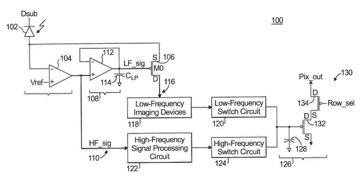
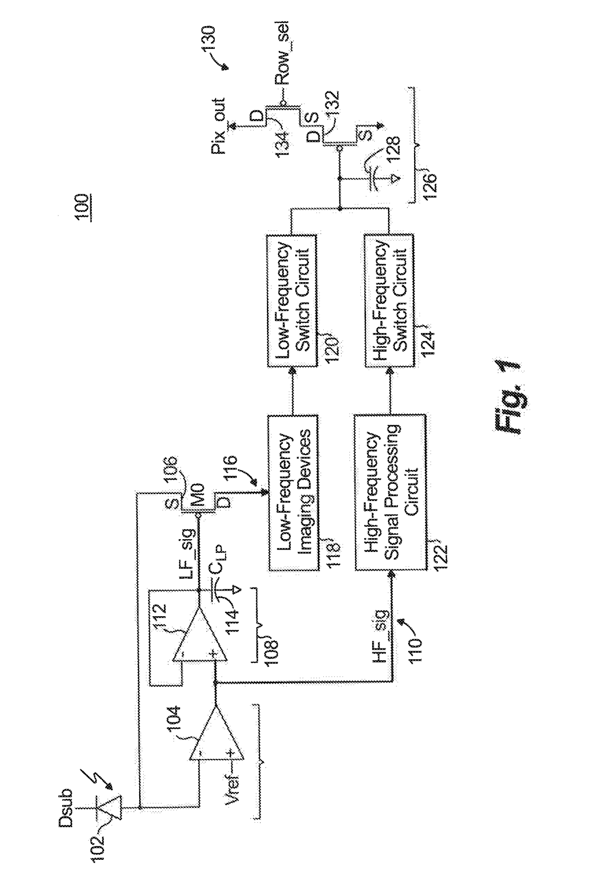
[0024]Reference will now be made to the drawings wherein like reference numerals identify similar structural features or aspects of the subject disclosure. For purposes of explanation and illustration, and not limitation, a schematic diagram of an exemplary embodiment of an enhanced pixel for wavefront sensing in accordance with the disclosure is shown in FIG. 1 and is designated generally by reference character 100. Other embodiments of an enhanced pixel in accordance with the disclosure, or aspects thereof, are provided in FIGS. 2-5, as will be described.

[0025]An example enhanced pixel 100 for wavefront sensing is shown in FIG. 1. The enhanced pixel 100 includes a low-frequency signal path for lower-frequency signals and a high-frequency signal path for high-frequency signals that can be processed for wavefront sensing. The enhanced pixel 100 includes a photodetector 102 that transmits charge signals which are received by a first-stage buffer 104 and a control device 106. The firs...


PUM


Abstract

A wavefront sensing pixel is provided. The wavefront sensing pixel includes a low-pass filter filtering a charge signal from a photodetector and outputting a control signal when low-frequency signals are detected in the charge signal, and a control device to control flow of the charge signal past the control device based on whether a low-frequency signal is detected in the charge signal. The wavefront sensing pixel further includes a low-frequency signal path that receives a flow of signals that flow past the control device, and a high-frequency signal path independent of the low-pass filter and the control device, the high-frequency signal path receiving high-frequency signals included in the charge signal.

Description

DEVELOPMENT[0001]This invention was made with government support under contract number FA9451-15-D-0023 awarded by the United States Air Force. The government has certain rights in the invention.BACKGROUND OF THE DISCLOSURE[0002]1. Field of the Invention[0003]The present disclosure relates to wavefront sensing, and more particularly to using wavefront sensing with an enhanced pixel.[0004]2. Description of Related Art[0005]Wavefront sensors are used to correct aberrations in images. For example, images generated during air travel can be subjected to turbulence that can cause the images to be laden with aberrations. Wavefront sensing can be applied to such aberration laden images to detect and remove aberrations and output an aberration-free image.[0006]For example, a telescope can enlarge an image during air travel, including when turbulence occurs. The turbulence can add aberrations to the enlarged image. The enlarged image can be output to optics including one or more lenses that m...

Claims


Application Information

Patent Timeline
IPC IPC(8): H04N5/357H04N5/3745H04N5/378
CPCH04N5/357H04N5/3745H04N5/378G02B26/06G01J9/00
Inventor LIN, MINLONGLUND, JOSHUAKUSCHAK, PATRICK
Owner SENSORS UNLTD
Why Eureka
Try Eureka