Aircraft fuel system

a fuel system and aircraft technology, applied in the direction of power plant fuel tanks, aircraft components, weight reduction, etc., can solve the problems of unusable fuel (also known as residual fuel), fuel which cannot be fed out of fuel, and extra empty weight, so as to reduce the range, passengers and cargo of aircraft operators' permitted use of aircra

Active Publication Date: 2017-07-27
AIRBUS OPERATIONS LTD
View PDF0 Cites 9 Cited by
  • Summary
  • Abstract
  • Description
  • Claims
  • Application Information

AI Technical Summary

Benefits of technology

[0006]A first aspect of the invention provides an aircraft fuel system comprising a bottom wall; a rib with a bottom edge joined to the bottom wall, the rib providing a boundary between first and second compartments, at least the first compartment being arranged to carry fuel when the system is in use; an open recess in the bottom edge of the rib; a rib sealing arrangement between the bottom edge of the rib and the bottom wall which prevents fuel from flowing across the bottom edge of the rib except at the open recess; a pump for pumping fuel from the first compartment; and a conduit coupled at one end to the open recess and at another end to the pump, the open recess and the conduit together providing a flow path for fuel to flow across the bottom edge of the rib from the first compartment into the pump, wherein the flow path is sealed so that the fuel flowing along the flow path is prevented from flowing out of the flow path into the second compartment.
[0012]The bottom edge of the rib may include a plurality of rib feet joining the bottom edge of the rib to the bottom wall, and the system further comprises: a plurality of sealed stringers which are carried by the bottom wall, each sealed stringer passing through a respective sealed recess between a respective pair of the plurality of rib feet; the rib sealing arrangement comprising a plurality of rib seal members, such as seal plates, each providing a seal which prevents fuel in the first compartment from flowing through a respective one of the sealed recesses into the second compartment; and a further pair of stringers which are carried by the bottom wall and pass through the open recess between a further pair of the plurality of rib feet, wherein the conduit is coupled at the one end to the open recess between the further pair of stringers. The stringers serve to stiffen the bottom wall.
[0014]Typically a lower boundary of the conduit is provided by the bottom wall. The conduit may be provided by the bottom wall, the further pair of stringers and a stringer cap fitted to the further pair of stringers in the second compartment, and the stringer cap is sealed to the rib and to the further pair of stringers so that the fuel flowing along the flow path is prevented from flowing out of the flow path into the second compartment.

Problems solved by technology

Conventional aircraft fuel systems therefore suffer from the problem of unusable fuel (also known as residual fuel)—that is, fuel which cannot be fed out of the fuel tank because it is trapped in a low or inaccessible region.
This extra empty weight reduces the aircraft operator's permitted usage of the aircraft in terms of range, passengers and cargo.

Method used


Image

  • Aircraft fuel system
  • Aircraft fuel system
  • Aircraft fuel system

Examples


Embodiment Construction

)

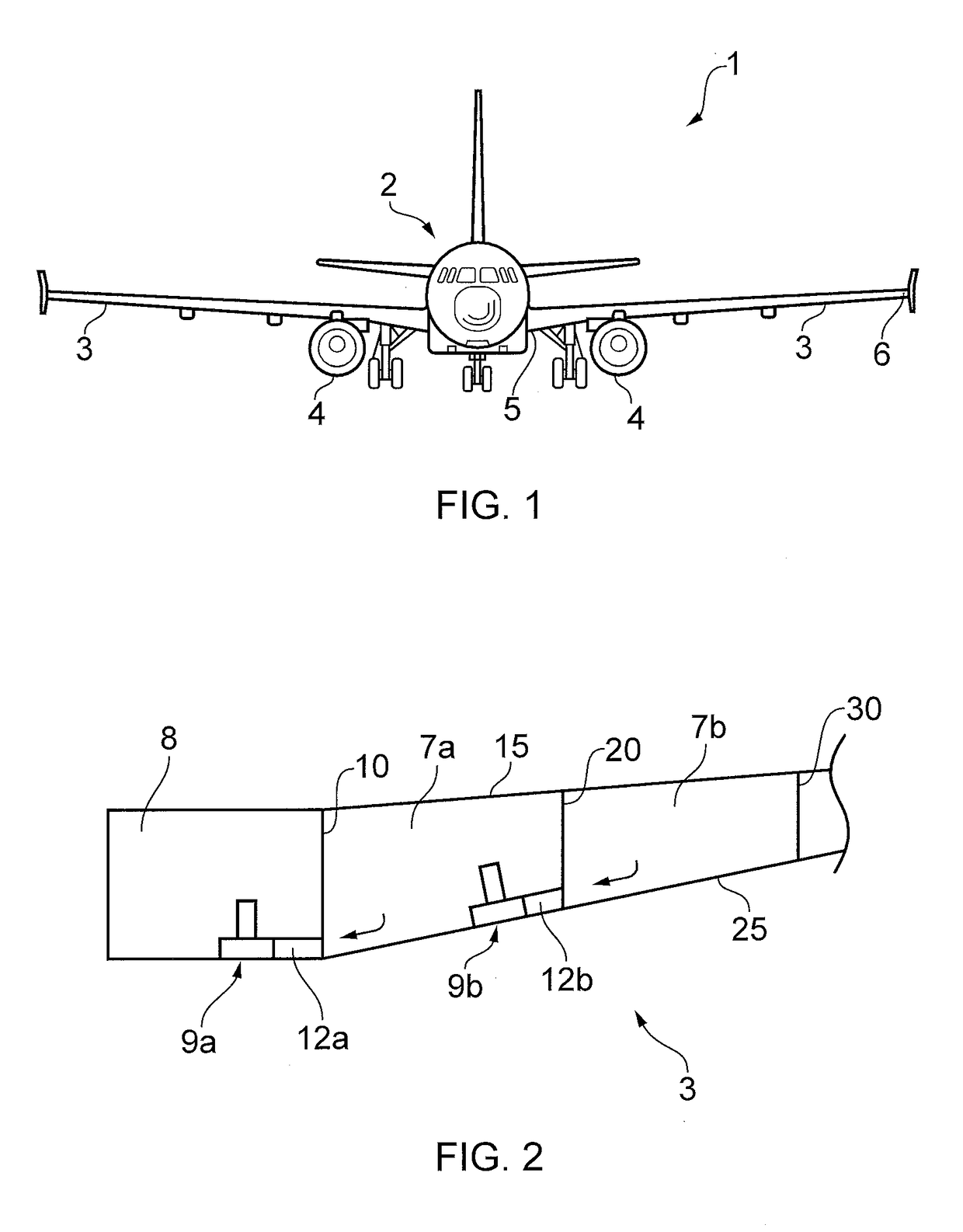
[0042]FIG. 1 shows an aircraft 1 including an embodiment of the fuel system of the present invention. The aircraft has a fuselage 2 and two wings 3 extending from either side of the fuselage 2. Each wing 3 extends in a spanwise direction from a wing root 5 where the wing meets the fuselage 2 to a wing tip 6. Each wing 3 is a dihedral wing, so the wing 3 is angled upwardly as it extends towards the wing tip 6. Engines 4 are located on the underside of each wing 3. FIG. 1 shows a single engine 4 on each wing, however the number and location of the engines may vary depending on the type of aircraft.

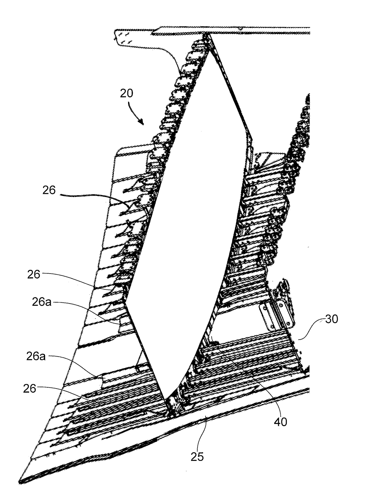
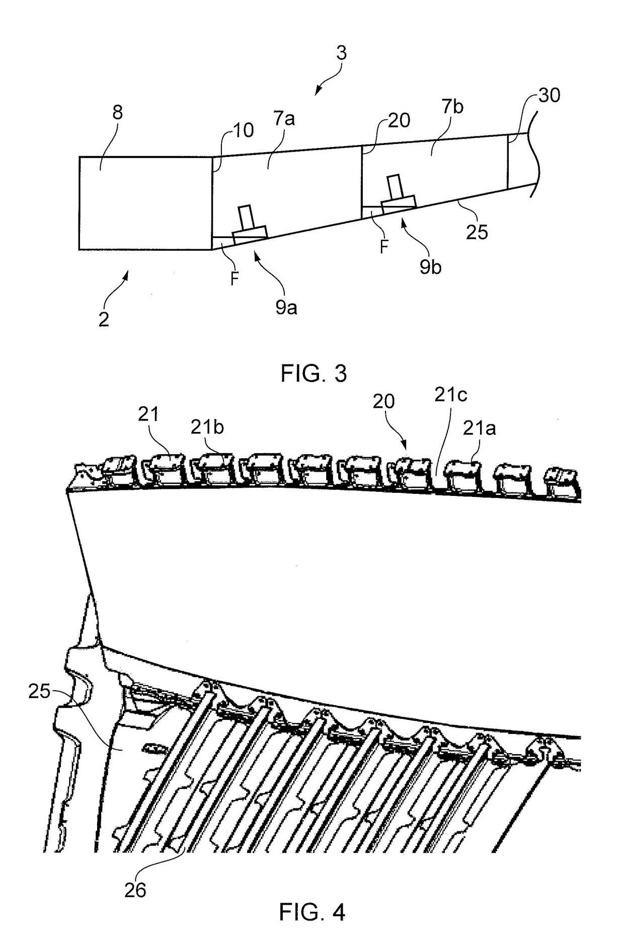
[0043]FIG. 2 is a schematic cross-sectional view through part of the fuel system of the aircraft 1, viewed from the front of the aircraft. FIG. 2 shows the fuel system within the port wing 3, the fuel system in the starboard wing being identical. The wing 3 includes a pair of spars (not shown) extending in a spanwise direction, and a number of substantially planar ribs 10, 20, 30 extending ...


PUM


Abstract

An aircraft fuel system has a bottom wall, and a rib with a bottom edge joined to the bottom wall. The rib provides a boundary between first and second compartments. At least the first compartment is arranged to carry fuel. An open recess is in the bottom edge of the rib and a rib sealing arrangement between the bottom edge of the rib and the bottom wall prevents fuel from flowing across the bottom edge of the rib except at the open recess. The system has a pump and a conduit coupled at one end to the open recess and at another end to the pump. The open recess and the conduit provide a fuel flow path across the bottom edge of the rib from the first compartment into the pump. The flow path is sealed to prevent fuel flowing out of the flow path into the second compartment.

Description

CROSS RELATED APPLICATION[0001]This application claims priority to Great Britain patent application 1601492.0 filed Jan. 27, 2016, the entirety of which is incorporated by reference.FIELD OF THE INVENTION[0002]The present invention relates to an aircraft fuel system.BACKGROUND OF THE INVENTION[0003]Fuel in an aircraft is typically stored in one or more fuel tanks or sealed compartments located in the interior space of the wings and fuselage of the aircraft. A fuel delivery system includes one or more fuel pumps arranged to draw fuel from the fuel tank(s) and deliver fuel to the engine(s).[0004]The location of the fuel pump within a fuel compartment can be restricted, for example by the irregular shape of the fuel compartment, internal structural components, or the physical size of the fuel pump. When the fuel pump is not located at the lowermost point in the compartment, the fuel pump is unable to empty the fuel compartment of fuel. Conventional aircraft fuel systems therefore suffe...

Claims


Application Information

Patent Timeline
Patent Type & Authority Applications(United States)
IPC IPC(8): B64D37/08B64C3/34
CPCB64C3/34B64D37/08Y02T50/40
Inventor MORGAN, ANGUS
Owner AIRBUS OPERATIONS LTD
Why Eureka
Try Eureka