Electric compressor

Active Publication Date: 2017-07-27
HANON SYST
View PDF5 Cites 5 Cited by
  • Summary
  • Abstract
  • Description
  • Claims
  • Application Information

AI Technical Summary

Benefits of technology

The present invention prevents the heat generation element from getting too hot, which could cause malfunctions or damage. This is done by using a low-temperature refrigerant to cool down the heated element, and it prevents the electric compressor from breaking down and getting disabled. This means that the invention allows for stable and safe use of the electric compressor.

Problems solved by technology

Because such heat generating elements typically have low durability, there is a problem in that it is relatively difficult to cool the elements in such a way that refrigerant flows directly through the elements.
If current higher than the control value is applied, the semiconductor element may be damaged.
However, there is a problem in that because the thickness of the support body is added to the thickness of the intake-side plate of the compressor, heat exchange between low-temperature refrigerant and the heat generating device cannot be reliably performed.
The above-mentioned problem causes malfunction due to overheating of the heat generating device.
Moreover, the addition of the separate support body increases the production cost.

Method used


Image

  • Electric compressor
  • Electric compressor
  • Electric compressor

Examples


Embodiment Construction

[0035]Hereinafter, an electric compressor according to an embodiment of the present invention will be described with reference to the attached drawings.

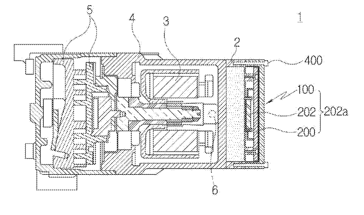
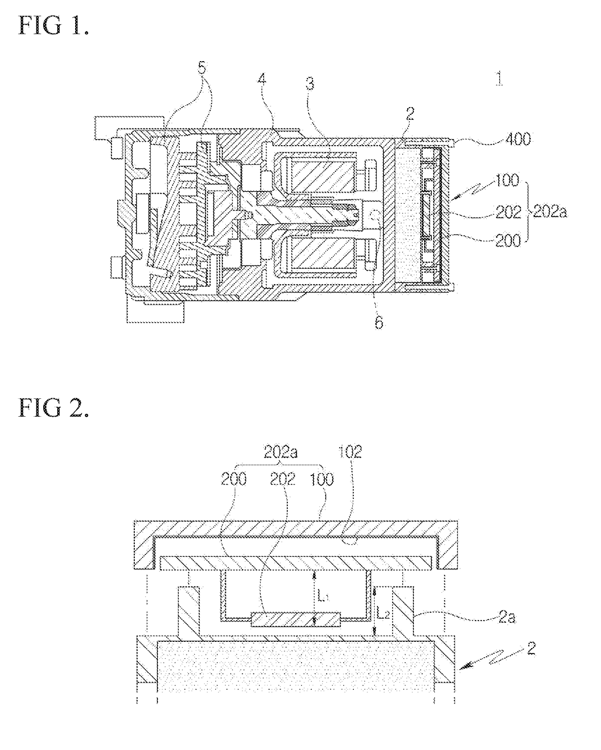
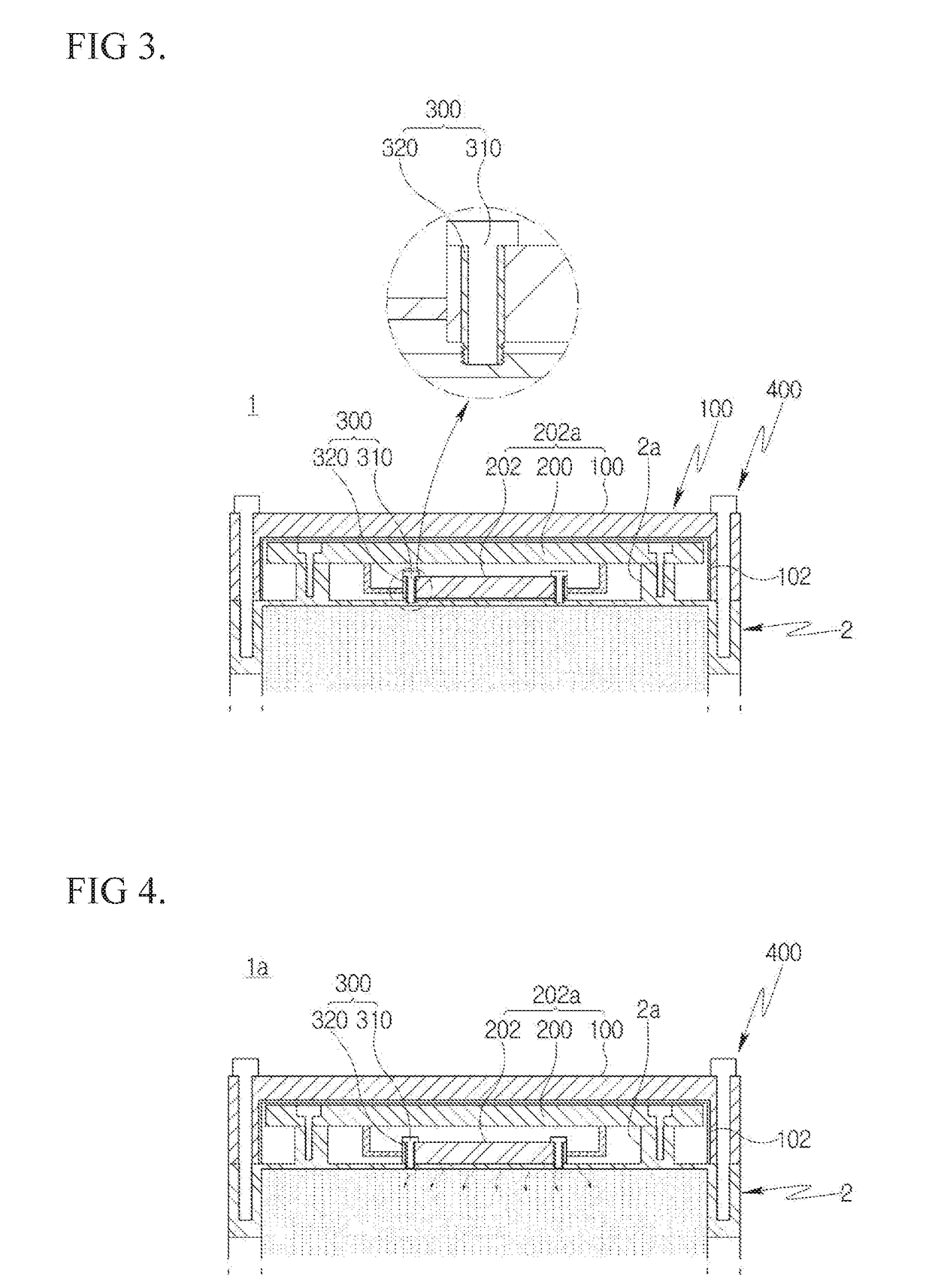
[0036]For reference, FIG. 1 is a longitudinal sectional view illustrating installation of an electric compressor in accordance with an embodiment of the present invention, FIG. 2 is a sectional view illustrating a process of mounting an inverter in a compressor housing in accordance with the embodiment of the present invention, FIG. 3 is a sectional view illustrating the inverter installed in the compressor housing in accordance with the embodiment of the present invention, and FIG. 4 is a sectional view illustrating a cooling operation for dissipating heat generated from the inverter in accordance with the embodiment of the present invention.

[0037]Referring to FIGS. 1 to 4, an electric compressor 1 includes a main body 4 which houses a motor unit 3 therein, an inverter cover 100 which covers an outer surface of the compressor housin...


PUM


Abstract

Disclosed herein is an electric compressor. The electric compressor includes an inverter cover which is mounted to an outer surface of a compressor housing in which compression of refrigerant is implemented, and a printed circuit board which is disposed inside the inverter cover and mounted with a plurality of heat generating elements that come into surface contact with one surface of the compressor housing and perform heat transfer with low-temperature refrigerant supplied into the compressor housing.

Description

CROSS-REFERENCE TO RELATED PATENT APPLICATIONS[0001]This patent application is a United States national phase patent application based on PCT / KR2015 / 010609 filed Oct. 7, 2015, which claims the benefit of Korean Patent Application No. 10-2014-0137751 filed Oct. 13, 2014, the disclosures of which are hereby incorporated herein by reference in their entirety.TECHNICAL FIELD[0002]Exemplary embodiments of the present invention relate to an electric compressor, and more particularly, to preventing an inverter installed in an electric compressor from overheating.BACKGROUND ART[0003]Generally, a compressor used in an air conditioning system for vehicles sucks refrigerant that has been evaporated by an evaporator, converts it into a high-temperature and high-pressure state, which can be easily liquefied, and then transfers it to a condenser. The compressor is configured to substantially compress refrigerant. Such compressors are classified into a reciprocating compressor which performs recip...

Claims


Application Information

Patent Timeline
IPC IPC(8): H02K9/10H02K11/33H02K5/20H02M1/00
CPCH02K9/10H02K7/14H02K11/33H02K5/20F04B49/20H02M1/00H02K5/203F04B39/06F04C29/047F04C2240/30F04C2240/808F04B39/121F25B49/022F04B35/04F05B2210/12F05B2210/14Y10S417/00
Inventor PARK, IL YOUNGBAEK, CHAN HOLEE, YOUNG HUN
Owner HANON SYST
Why Eureka
Try Eureka