Substrate accommodating tray

Active Publication Date: 2005-07-14
SHARP KK +1
View PDF6 Cites 2 Cited by
  • Summary
  • Abstract
  • Description
  • Claims
  • Application Information

AI Technical Summary

Benefits of technology

[0022] According to one aspect of the invention, a substrate accommodating tray having a flat support member for mounting a substrate is provided. The support member has a surface resistance of less than 1014Ω / □, and comprises a resin foam body capable of preventing the resin from being transferred onto the substrate.
[0028] The substrate accommodating tray of the present invention includes the conductive support member made with a conductive resin foam body where the resin is not transferred onto the substrate. Therefore, this tray can prevent the resin from being transferred onto the substrate when the substrate is transported and stored under high temperature and humidity condition. In addition, since the accommodated substrate does not break and adhere dust, this tray can prevent the processing yield from decreasing when the substrate is processed to a panel or the like.
[0029] Furthermore, since an antistatic function can be stabilized for a long time, this tray can be stably used for a long time.

Problems solved by technology

Such a large and thin glass substrate easily warps.
When a plurality of such glass substrates are vertically accommodated in the box with an interval, the glass substrates may warp and contact each other and break during transportation.
Since a plurality of glass substrates accommodated in a glass substrate accommodating box needs to have the suitable space between the substrates, the number of glass substrates which can be accommodated in a glass substrate accommodating box having a prescribed size is limited.
Such a space for the adsorption pads increases the size of the substrate accommodating tray.
Further, since this substrate accommodating section is formed in a lattice shape, the strength of the tray has a limit and thus the number of substrate trays stacked vertically is limited.
However, when the glass substrate is mounted on the support member without warping, the support member contacts with a large area of the glass substrate, and thus the glass substrate may break during transportation depending on the characteristic of the support member.
However, even when the support member is made with the synthetic resin foam body, there are the following problems.
That is, the surface of the glass substrate is damaged by the support member depending on the characteristic thereof.
Further, a dust is generated due to the friction with the glass substrate and adheres to the glass substrate.
However, such a foam laminated sheet of an antistatic polypropylene resin has insufficient elasticity and high rigidity, i.e., high hardness, and thus damages the glass substrate or generates dust due to the friction with the glass substrate.
In the unfoamed polypropylene resin layer incorporated with an antistatic agent, the antistatic agent is easily released due to the friction with the glass substrate, and thus a charging function is not stabilized for a long period of time.
Furthermore, since the unfoamed polypropylene resin layer has a laminated structure of a foam layer and an unfoamed layer, it cannot be easily produced.
This molded object is broken by an impact when supporting a heavy object such as a glass substrate, since brittleness on the foam board surface increases, i.e., the surface becomes weak.

Method used


Image

  • Substrate accommodating tray
  • Substrate accommodating tray
  • Substrate accommodating tray

Examples


Embodiment Construction

[0033] Hereinafter, the present invention will be described by way of illustrative examples with reference to the accompanying drawings.

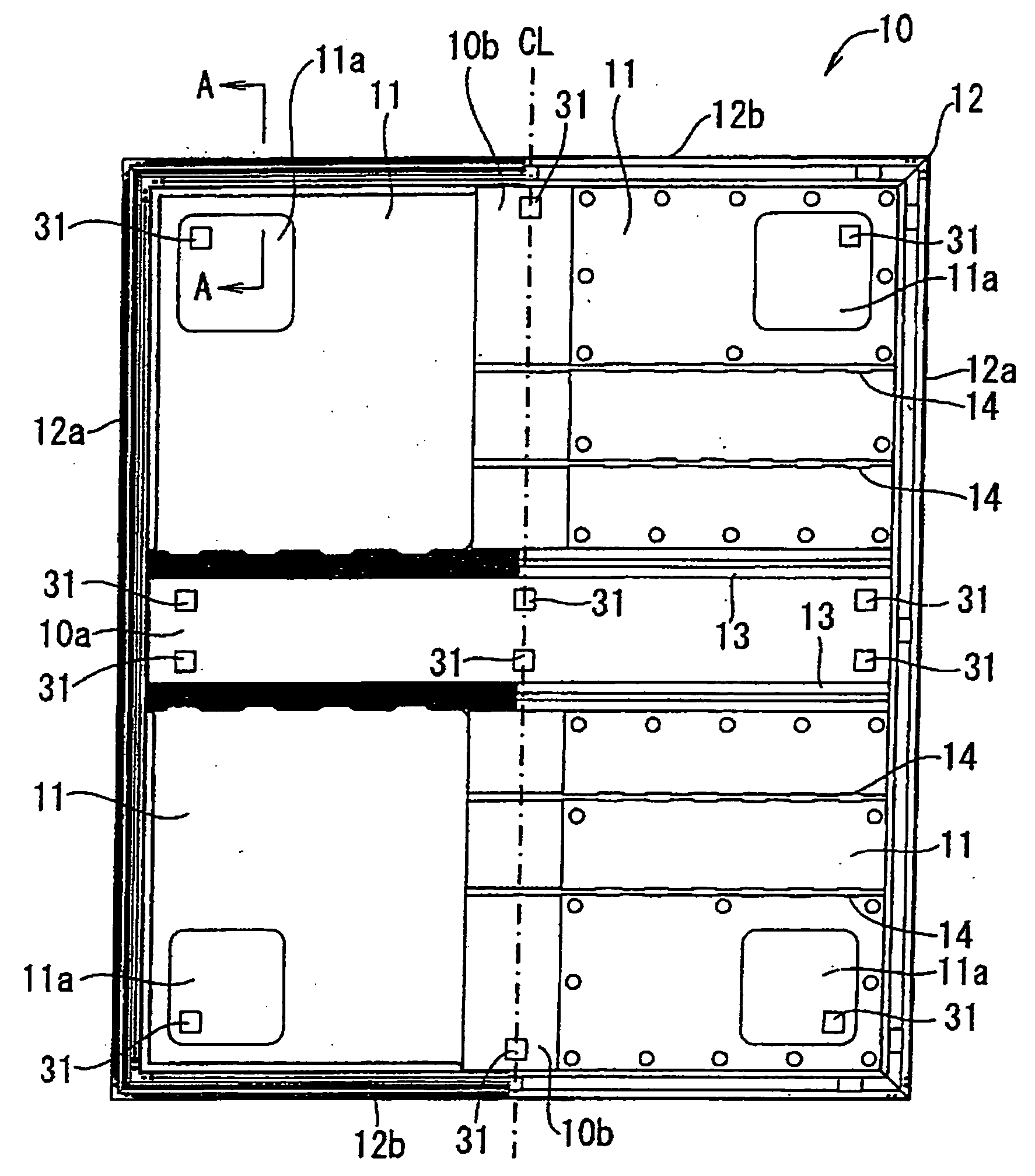
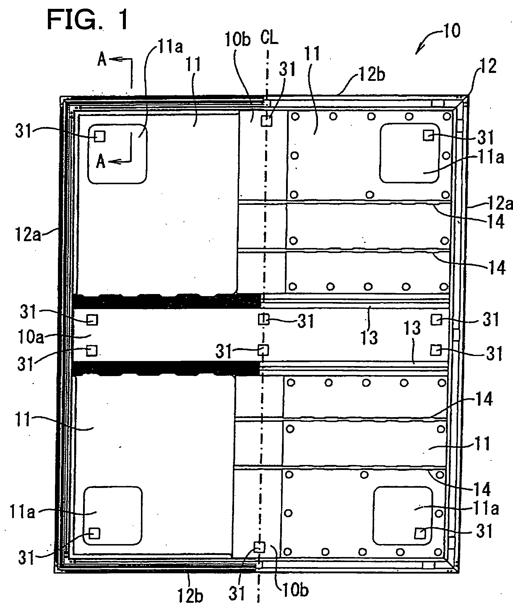
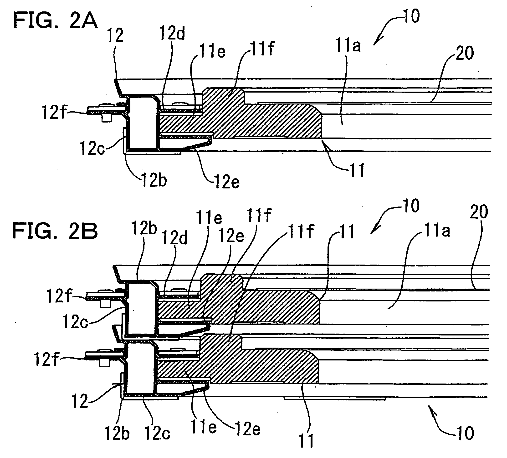
[0034]FIG. 1 is a plane and bottom view of an exemplary embodiment of a substrate accommodating tray used for the present invention. FIG. 2(a) is a partial cross-sectional view of the substrate accommodating tray taken along line A-A in FIG. 1. In FIG. 1, the left side of the dashed line CL at the center of the figure is a plane view and the right side is a bottom view.

[0035] A substrate accommodating tray 10 is used for accommodating and transporting a rectangular glass substrate for a display which is used a liquid crystal display panel; specifically, a rectangular or square glass substrate having a side length of 1.3 m or more and a thickness of 0.7 mm or less.

[0036] The substrate accommodating tray 10 includes a frame member 12 having a rectangular shape, and four flat support members 11, which are arranged side by side in parallel to the hor...


PUM

PropertyMeasurementUnit
Electrical resistanceaaaaaaaaaa
Electrical conductoraaaaaaaaaa

Abstract

A substrate, for example, a display glass substrate, can be transported and stored with high efficiency, without breaking and adhering dust. A substrate accommodating tray includes a frame member 12 formed to have a larger rectangular frame shape than a glass substrate and four support members 11, having elasticity, formed in an inside region surrounded by the frame member 12. The frame member 12 is formed with a pair of longitudinal direction frames 12a and a pair of width direction frames 12b, and the four support members 11 are arranged while being engaged with the frame member 12. Each support member 11 includes conductive polyethylene foam, which is molded by coating conductive particles on synthetic resin beads as a raw material and foaming it in this state. Therefore, transferring of the resin onto the glass substrate can be prevented during transportation and storage.

Description

[0001] This Nonprovisional application claims priority under 35 U.S.C. §119(a) on Patent Application No. 2003-422758 filed in Japan on Dec. 19, 2003, the entire contents of which are hereby incorporated by reference. BACKGROUND OF THE INVENTION [0002] 1. Field of the Invention [0003] The present invention relates to a substrate accommodating tray used for transporting square or rectangular substrates, such as a glass substrate for a display or the like. The glass substrate is used for producing a display panel of, for example, a liquid crystal display device. [0004] 2. Description of the Related Art [0005] A display panel for a liquid crystal display device usually includes a pair of display glass substrates opposed to each other and sealed together, and a liquid crystal material sealed between the pair of glass substrates. In order to produce such a display panel, glass substrates are transported to a display panel production plant. For transporting the glass substrates, a glass su...

Claims


Application Information

Patent Timeline
IPC IPC(8): B65D19/00B65D85/86B65D85/30B65D85/48B65G49/06G02F1/13H01L21/673H01L21/68H05K7/00
CPCB65G49/061H01L21/673B65G2249/02Y10T428/24999Y10T428/249981Y10T428/249985G02F1/13
Inventor YOSHIZAWA, TAKENORISHIBATA, HIROTO
Owner SHARP KK
Why Eureka
Try Eureka