
Cockpit display systems and methods for generating cockpit displays including enhanced flight visibility indicators

a display system and display technology, applied in the field ofcockpit display systems, can solve the problems of difficult for pilots to accurately determine whether, and pilots may be forced to resort to imprecise, subjective judgments, etc., and achieve enhanced flight visibility, enhanced flight visibility, and enhanced flight visibility

Active Publication Date: 2017-07-27
HONEYWELL INT INC
View PDF15 Cites 12 Cited by
  • Summary
  • Abstract
  • Description
  • Claims
  • Application Information

AI Technical Summary

Benefits of technology

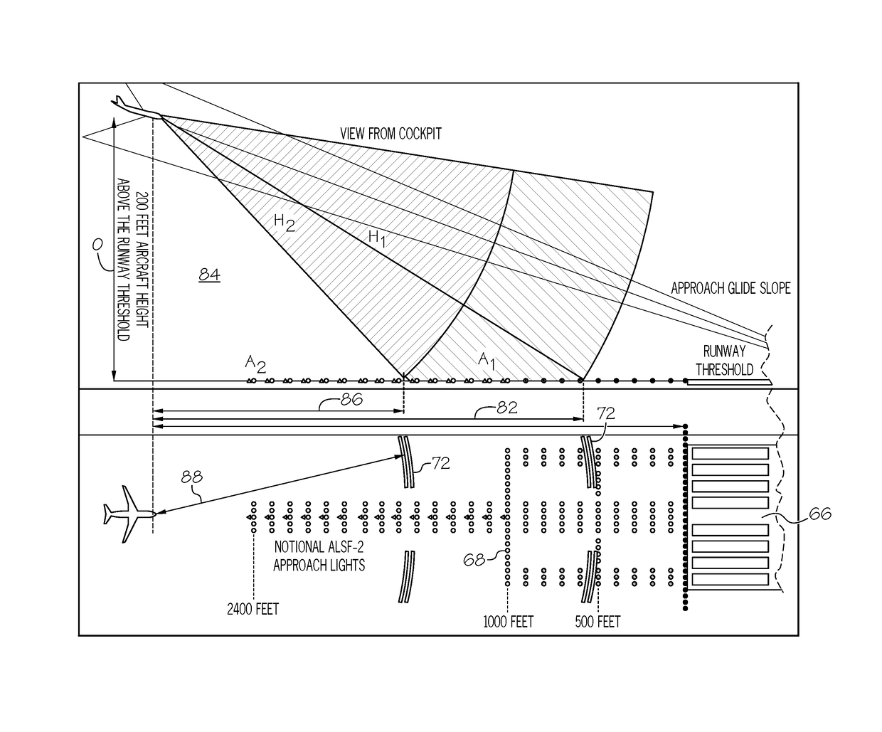
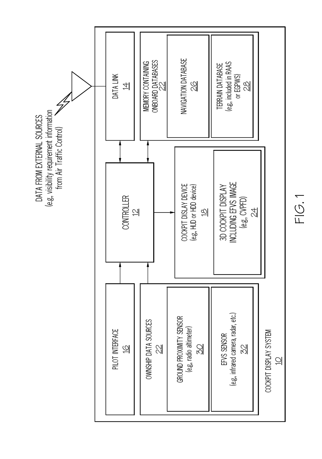
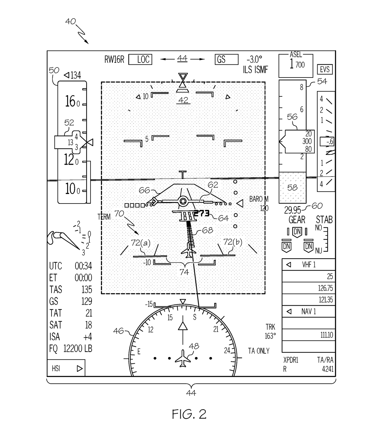
Cockpit display systems have been developed that can show a 3D image of the surrounding environment, including useful information for improving flight visibility. The systems use sensors to monitor the region in front of the aircraft and display the information on the cockpit display device. The controller determines the specific requirements for enhanced flight visibility when approaching a runway for landing and can generate a visual representation of this information on the display. This can help improve the pilot's ability to see the runway and safely land the aircraft.

Problems solved by technology

While such regulations are clear, it may be difficult for a pilot to accurately determine whether such regulations are satisfied under IMC as visual references for estimating the distance between the aircraft and lighted objects ahead of the aircraft are often sparse or nonexistent.
A pilot may consequently be forced to resort to imprecise, subjective judgments when performing this task.

Method used


Image

  • Cockpit display systems and methods for generating cockpit displays including enhanced flight visibility indicators
  • Cockpit display systems and methods for generating cockpit displays including enhanced flight visibility indicators
  • Cockpit display systems and methods for generating cockpit displays including enhanced flight visibility indicators

Examples


Embodiment Construction

[0013]The following Detailed Description is merely exemplary in nature and is not intended to limit the invention or the application and uses of the invention. The term “exemplary,” as appearing throughout this document, is synonymous with the term “example” and is utilized repeatedly below to emphasize that the description appearing in the following section merely provides multiple non-limiting examples of the invention and should not be construed to restrict the scope of the invention, as set-out in the Claims, in any respect.

[0014]The following describes cockpit display systems and methods for generating three dimensional (3D) cockpit displays including symbology useful in assessing whether enhanced flight visibility requirements are satisfied during approach and landing. The 3D cockpit display can be, for example, a Combined Vision Primary Flight Display (CVPFD) or other display including or consisting of an Enhanced Flight Vision System (EFVS) image. During operation, embodimen...


PUM


Abstract

Cockpit display systems and methods are provided for generating cockpit displays including symbology useful in assessing whether enhanced flight visibility requirements are satisfied during approach and landing. In one embodiment, the cockpit display system includes an Enhanced Flight Vision System (EFVS) sensor configured to monitor a region forward of the aircraft for runway reference features, a cockpit display device on which an EFVS image is generated utilizing EFVS sensor data, and a controller coupled to the EFVS sensor and to the display device. The controller determines an enhanced flight visibility requirement for a runway approached by the aircraft, and then visually indicates on the EFVS image whether enhanced flight visibility requirement is currently satisfied by, for example. generating an enhanced flight visibility indicator (EFVI) graphic on the EFVS image visually identifying a ground location beyond which the appearance of a runway reference feature satisfies the enhanced flight visibility requirement.

Description

TECHNICAL FIELD[0001]The following disclosure relates generally to cockpit display systems and, more particularly, to cockpit display systems and methods for generating three dimensional cockpit displays including symbology useful in assessing whether enhanced flight visibility requirements are satisfied during approach and landing.BACKGROUND[0002]An Enhanced Flight Vision System (EFVS) generates a three dimensional image of a flight environment utilizing sensor data received from a forward-looking sensor carried by an aircraft. The forward-looking sensor can be, for example, an infrared camera or a millimeter wave radar located within a radome beneath the aircraft. The EFVS image can be generated on either a Head Up Display (HUD) or a Head Down Display (HDD) device. Additionally, in certain implementations, the EFVS image can be combined with a database-dependent Synthetic Vision System (SVS) image to yield a Combined Vision System (CVS) display. For example, a Combined Vision Prim...

Claims


Application Information

Patent Timeline
IPC IPC(8): H04N13/04G08G5/00B64D43/00
CPCH04N13/0402B64D43/00G06F1/163G06T15/005G08G5/0047G01C23/005H04N13/302G08G5/025G08G5/0021
Inventor WYATT, IVAN SANDYTUNHEIM, DAVID ALLENHE, GANG
Owner HONEYWELL INT INC
Learn More