Supercharge Your Innovation With Domain-Expert AI Agents!

Projector and projection display device

a projection display device and projector technology, applied in the direction of picture reproducers, polarising elements, instruments using projection devices, etc., can solve the problem of not being able to use a spatial light modulator that forms a modulated imag

Inactive Publication Date: 2017-07-27
DAI NIPPON PRINTING CO LTD
View PDF2 Cites 0 Cited by
  • Summary
  • Abstract
  • Description
  • Claims
  • Application Information

AI Technical Summary

Benefits of technology

This design enables the use of a variety of spatial light modulators, reduces the size and complexity of the projector, and effectively obscures speckles, providing a more viewer-friendly and versatile 3D image projection solution.

Problems solved by technology

Thus, it is not possible to use a spatial light modulator that forms a modulated image depending on the polarization state of illumination light, for example, a liquid crystal micro-display that forms a modulated image by illumination light of a particular polarization component.

Method used


Image

  • Projector and projection display device
  • Projector and projection display device
  • Projector and projection display device

Examples


Embodiment Construction

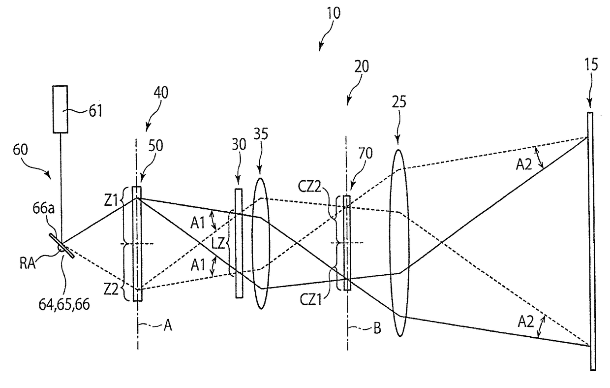
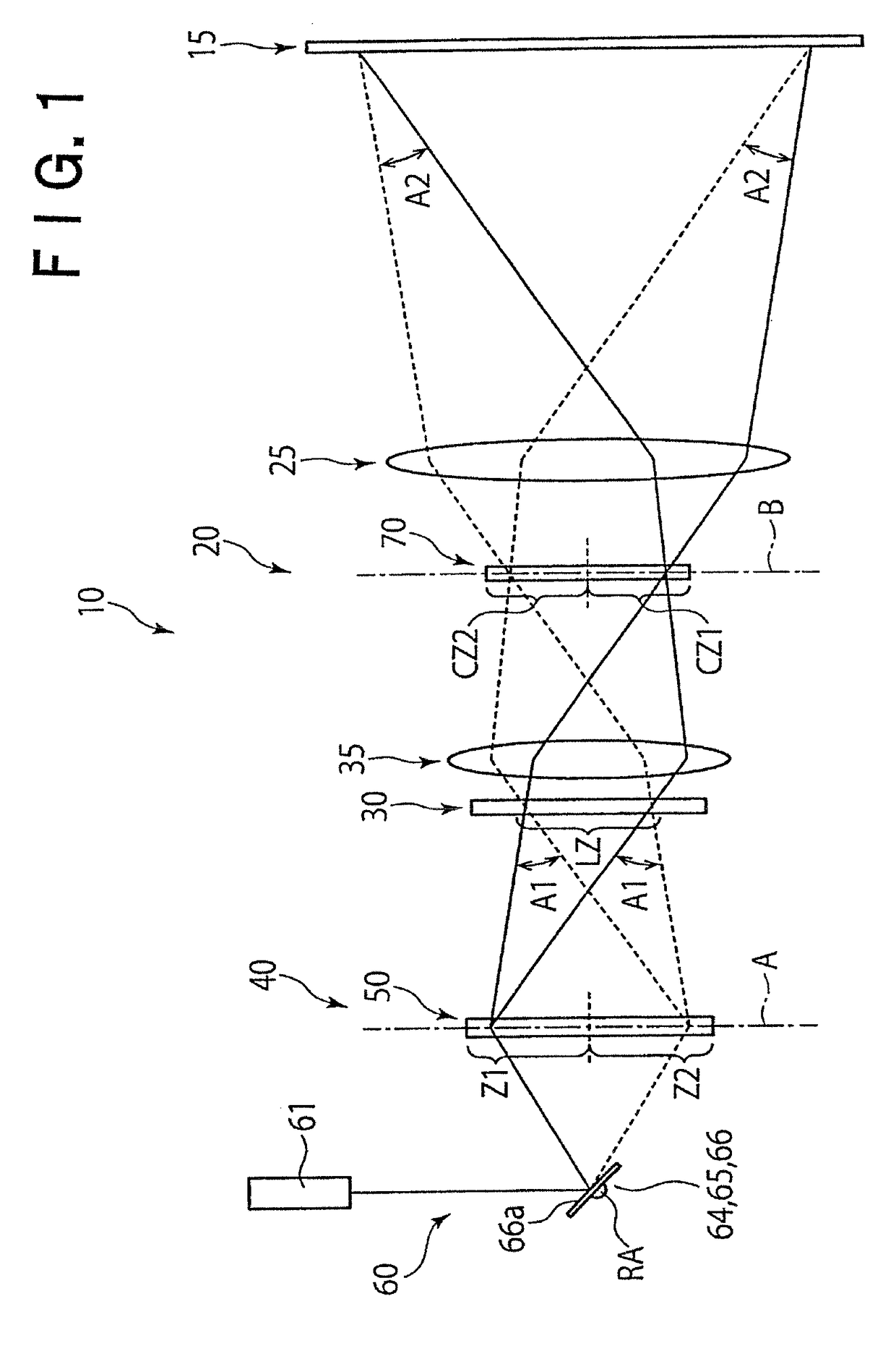
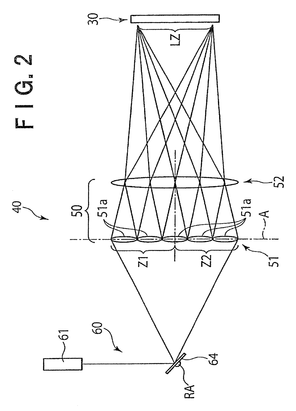
[0027]Preferred embodiments of the present invention will now be described with reference to the drawings. In the drawings attached hereto, scales, horizontal to vertical dimensional ratios, etc. are exaggeratingly modified from those of the real things for the sake of illustration and easier understanding.

[0028]The projection display device 10 shown in FIG. 1 includes a screen 15 and a projector 20 for projecting image light. The projector 20 includes an optical element 50 including a first region Z1 and a second region Z2 and which diffuses light that has entered the regions Z1, Z2, an irradiation device 60 for irradiating the first region Z1 and the second region Z2 of the optical element 50 with light in a time-divisional manner, a polarization control means 70 for controlling the polarization state of light from the optical element 50, and a spatial light modulator 30 disposed in a light path from the optical element 50 to the polarization control means 70. The projector 20 als...


PUM


Abstract

A projector includes: an optical element including first and second regions and which diffuses light that has entered the regions; an irradiation device for irradiating the first and second regions with light in a time-divisional manner; a polarization control means disposed on a plane (B) which is conjugate to a plane (A) on which the optical element is disposed; and a spatial light modulator disposed in a light path from the optical element to the polarization control means and which is illuminated with light that has been diffused by the first and second regions. The polarization control means controls the polarization state of light so that light that has been diffused by the first region becomes light of a first polarization component, and light that has been diffused by the second region becomes light of a second polarization component which differs from the first polarization component.

Description

CROSS REFERENCE TO RELATED APPLICATIONS[0001]This application is a continuation of U.S. application Ser. No. 14 / 899,612, filed Dec. 18, 2015, which in turn is the National Stage of International Application No. PCT / JP2014 / 066250, filed Jun. 19, 2014, the entireties of which are incorporated herein by reference.FIELD OF THE INVENTION[0002]The present disclosure relates to a projector for projecting light and a projection display device including the projector, and more particularly to a projector capable of projecting image lights formed of lights of different polarization components, and a projection display device including the projector.BACKGROUND OF THE INVENTION[0003]As disclosed e.g. in WO 2012 / 033178A1, research and development has been conducted on a projection display device which projects image lights formed of lights of different polarization components. Such a projection display device can be used as a device which, in combination with dedicated glasses, displays three-di...

Claims


Application Information

Patent Timeline
Patent Type & Authority Applications(United States)
IPC IPC(8): H04N13/04G02B5/02G03B35/26G02B5/30H04N9/31G02B27/48G02B3/00H04N13/363H04N13/388
CPCH04N13/0438H04N13/0459G02B27/48G02B5/0252H04N9/3161G02B5/3083H04N9/3164G03B35/26G02B3/0006G03B21/2013G03B21/2073G03B21/208H04N9/3152H04N13/363H04N13/388H04N13/337G02B30/25H04N13/341G02B5/3033G02B5/32
Inventor KURASHIGE, MAKIO
Owner DAI NIPPON PRINTING CO LTD
Features
  • R&D
  • Intellectual Property
  • Life Sciences
  • Materials
  • Tech Scout
  • Unparalleled Data Quality
  • Higher Quality Content
  • 60% Fewer Hallucinations
Learn More