
Vibrating pallet system for automated wire insertion

a pallet system and wire insertion technology, applied in the direction of coupling device details, cable/conductor manufacturing, coupling device connection, etc., can solve the problems of high failure rate of automated wire insertion machines, high failure rate of wire insertion, and failure of insertion, so as to reduce the total production time, reduce the failure rate of wire insertion, and increase the tolerance of the cavity

Active Publication Date: 2017-08-03
THE BOEING CO
View PDF5 Cites 3 Cited by
  • Summary
  • Abstract
  • Description
  • Claims
  • Application Information

AI Technical Summary

Benefits of technology

The patent is about methods and devices for inserting wires into fixtures of structures or components. It includes a grommet, a gripper, and a vibration element. The vibration helps to shift the position of the cavity during wire insertion, increasing tolerance and reducing failure rates. The vibration also pivots the contact, making it easier to insert the wire. Overall, the patent aims to make wire insertion easier and more efficient.

Problems solved by technology

The tolerance stack up of the connector manufacturer, however, may place the connector cavity locations outside of the tolerance of the programmed positions of the automated wire insertion machine, thus causing misalignments and / or high failure rates.
Automated wire insertion machines have high failure rates due to the collisions between the wire contact and the grommet or dielectric face of the connector.
Many of these wire insertion failures are attributed to the interference fit and high friction of the contact in the compliant grommet material.
As such, there may be a misalignment between the master key on the connector shell and the grommet cavity holes.
Other misalignments may occur due to a translational error of the grommet within the shell as the grommet is glued into the connector by hand.
The tolerance stack up of the connector part induces numerous wire insertion failures with the use of an automated wire insertion machine.
The lack of rigidity in the wire makes fully seating the wire in the connector difficult.
If the wire contact and the dielectric cavity are not perfectly aligned, numerous insertion failures may occur.
The high friction in the grommet makes it difficult to effectively move the contact to locate the dielectric hole.
Furthermore, multiple failed attempts are time consuming and oftentimes slow production as hundreds or thousands of wires may be required to be inserted in a given system.

Method used


Image

  • Vibrating pallet system for automated wire insertion
  • Vibrating pallet system for automated wire insertion
  • Vibrating pallet system for automated wire insertion

Examples


Embodiment Construction

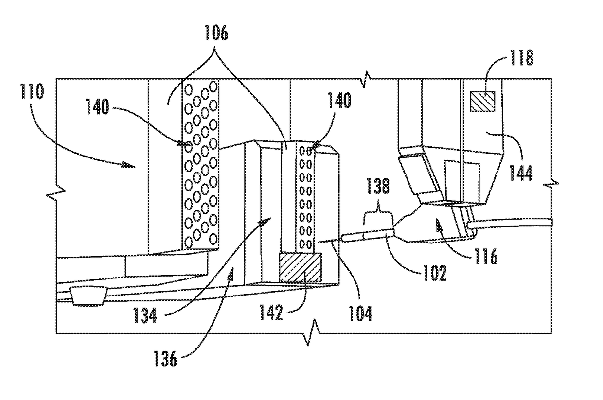
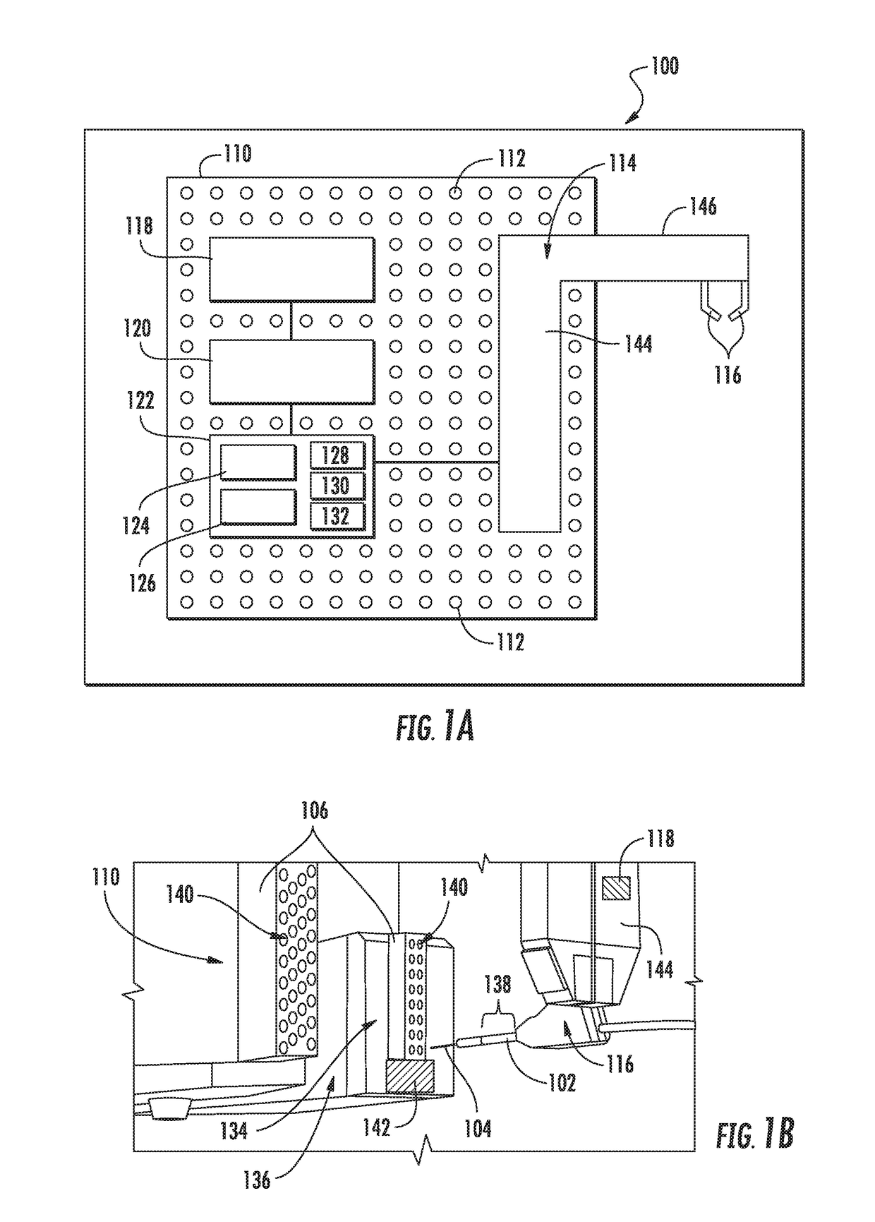
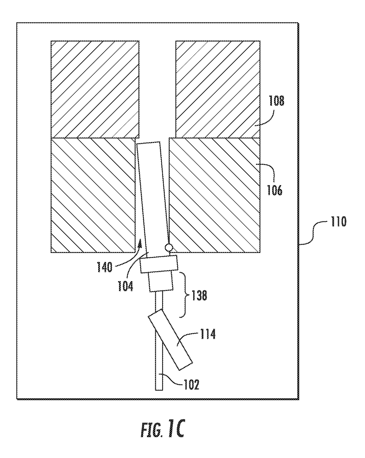
[0016]Examples disclosed herein generally relate to methods and apparatus for the insertion of one or more wires into a cavity of a fixture of a structure or component. The wire insertion apparatus includes a grommet, a gripper adapted to interface with the grommet, and at least a first vibrating element. The first vibrating element is connected to and vibrates one or more of the apparatus, the grommet, the gripper, the wire, and / or a component of the apparatus. Vibration, induced in any direction, enables the cavities to shift position during insertion relative to the contact, thus increasing the tolerance of the cavity, reducing the failure rate of wire insertion, and reducing total production time. The vibration breaks the static friction of the contact in the grommet or dielectric opening, creates the positive locating required to insert the contact in the grommet and / or dielectric, and / or pivots the contact.

[0017]FIGS. 1A and 1B schematically illustrate a wire insertion system ...


PUM

PropertyMeasurementUnit
distanceaaaaaaaaaa
frictionaaaaaaaaaa
rigidityaaaaaaaaaa

Abstract

Examples disclosed herein generally relate to methods and apparatus for the insertion of one or more wires into a cavity of a fixture of a structure or component. The wire insertion apparatus includes a grommet, a gripper adapted to interface with the grommet, and at least a first vibrating element. The first vibrating element is connected to and vibrates one or more of the apparatus, the grommet, the gripper, the wire, and / or a component of the apparatus. Vibration, induced in any direction, enables the cavities to shift position during insertion relative to the contact, thus increasing the tolerance of the cavity, reducing the failure rate of wire insertion, and reducing total production time. The vibration breaks the static friction of the contact in the grommet or dielectric opening, creates the positive locating required to insert the contact in the grommet and / or dielectric, and / or pivots the contact.

Description

BACKGROUND[0001]Field[0002]The present disclosure generally relates to automated wire insertion systems for manufacturing processes, such as aircraft or electronics manufacturing. More specifically, the present disclosure generally relates to a system and method for the insertion of a wire into a fixture using vibratory motion.[0003]Description of the Related Art[0004]Typical wire insertion automation machines require very tight tolerances between the expected (programmed) grommet cavity location and the actual position when mounted to the pallet. Currently, connectors are attached to the pallet by a rigid threaded fixture that aligns the connector by its outer shell or with a connector friction post. The tolerance stack up of the connector manufacturer, however, may place the connector cavity locations outside of the tolerance of the programmed positions of the automated wire insertion machine, thus causing misalignments and / or high failure rates. Automated wire insertion machines ...

Claims


Application Information

Patent Timeline
Patent Type & Authority Applications(United States)
IPC IPC(8): H01R43/20
CPCH01R43/20Y10T29/42Y10T29/49174Y10T29/53243Y10T29/53213Y10T29/53209H01R33/90H01R39/64H01R43/28H01B13/01236H01R2201/20H01R43/0207H01R13/665H10N30/88
Inventor HELMICK, EERIK J.MITCHELL, BRADLEY J.
Owner THE BOEING CO
Learn More