
Network service header used to relay authenticated session information

a network service and session information technology, applied in the field of network communication, can solve the problems of current methods not working with respect to service function chains in layer 2 (, l2) and layer 3 (, ) oriented services

Active Publication Date: 2017-08-03
CISCO TECH INC
View PDF3 Cites 4 Cited by
  • Summary
  • Abstract
  • Description
  • Claims
  • Application Information

AI Technical Summary

Benefits of technology

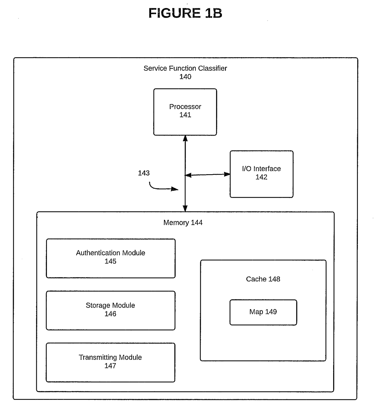
The patent text describes a system and method for authenticating packets and traffic on a network's service topology layer. This is useful for ensuring that users and clients are authenticated and validated before performing various service functions on the network. The system includes a service function classifier, an authentication node, and service nodes, which work together to authenticate packets and establish sessions with clients. The system also includes a map that helps service nodes identify and validate clients based on the information added to the network's service headers. Overall, this system and method improve network security and efficiency by authenticating and validating packets and traffic on the service topology layer.

Problems solved by technology

However, current methods do not work with respect to service function chains in Layer 2 (“L2”) and Layer 3 (“L3”) oriented services, such as in the service topology layer of a network.

Method used


Image

  • Network service header used to relay authenticated session information
  • Network service header used to relay authenticated session information
  • Network service header used to relay authenticated session information

Examples


example service topology

Layer

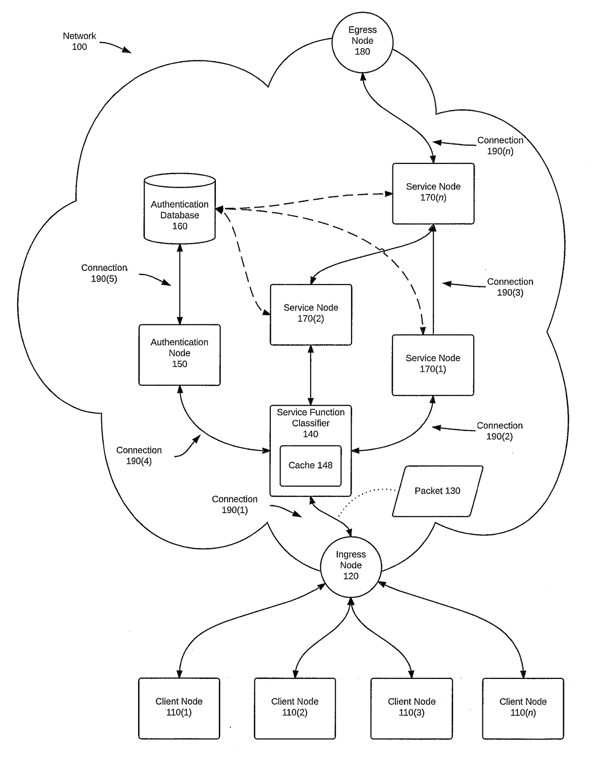
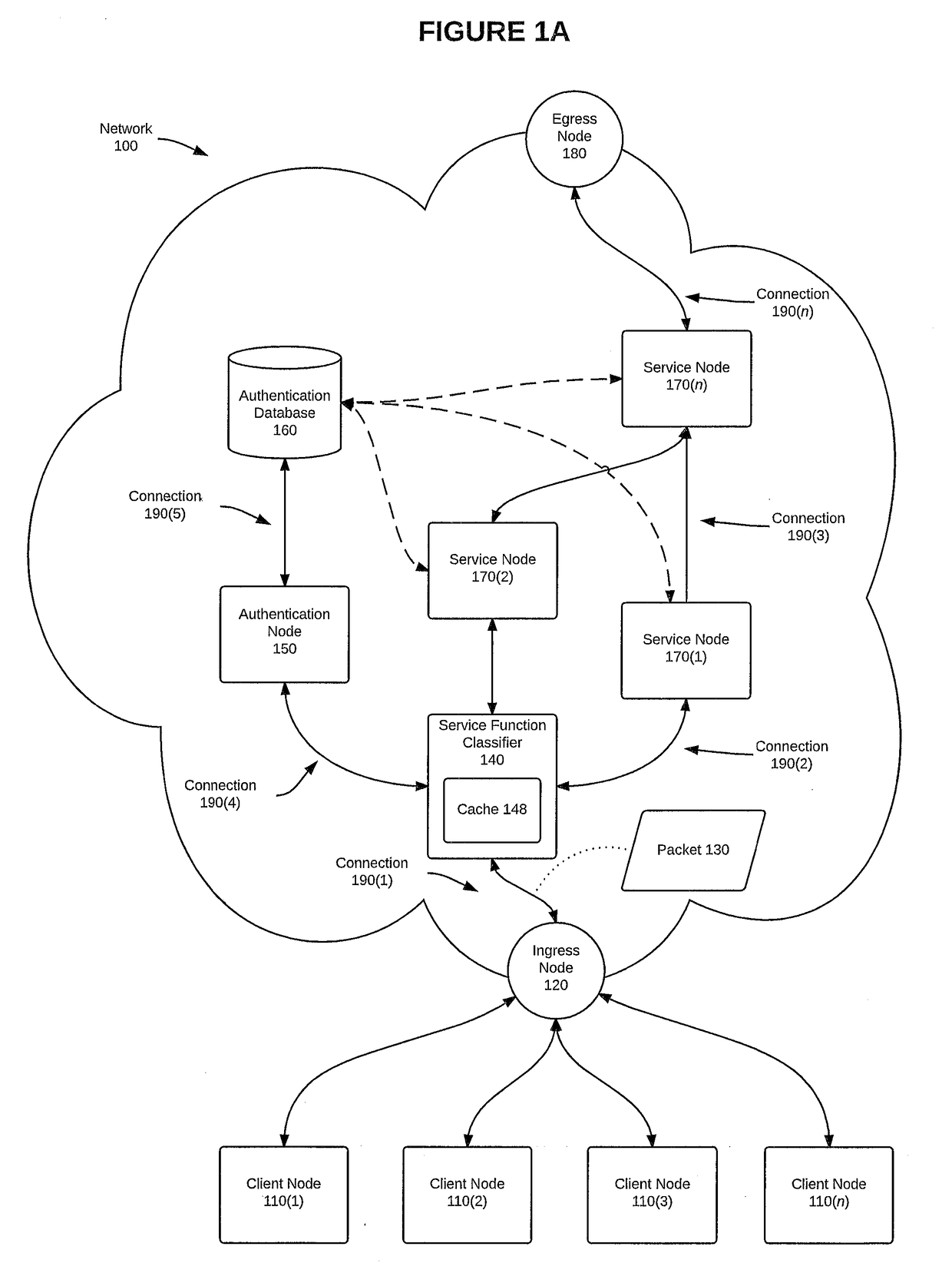
[0020]FIG. 1A is a block diagram of a service topology layer of a network 100, according to one embodiment. Network 100 is configured to authenticate a session by using the systems and methods disclosed herein. More specifically, FIG. 1A depicts a group of client nodes 110(1)-110(n) (collectively, “client nodes 110”) connected to an ingress node 120 of network 100. Client nodes 110 can be any computing device capable of being used in accordance with this disclosure, such as, e.g., a gateway, router, or switch (collectively, “router(s)”); or a personal computer, laptop computer, or mobile communication device such as a cell phone or tablet computer (collectively, “personal computer(s)”). Ingress node 120 can also be any computing device capable of being used in accordance with this disclosure, such as, e.g., a router, a server, or a personal computer.

[0021]A service topology layer can be configured to provide one or more service functions to a packet, such as packet 130. Each pa...

example networking devices

[0061]FIG. 5 is a block diagram illustrating components of an example networking device 500, which depicts (at least in part) one configuration of a network device or a network routing element (e.g., a hub, router, switch, or similar device). In this depiction, networking device 500 includes a number of line cards (line cards 502(1)-502(N)) that are communicatively coupled to a control module 510 (which can include a forwarding engine, not shown) and a traffic control (or flow control) processor 520 via a data bus 530 and a result bus 540. Line cards 502(1)-(N) include a number of port processors 550(1,1)-550(N,N) which are controlled by port processor controllers 560(1)-560(N). It will also be noted that control module 510 and route processor 520 are not only coupled to one another via data bus 530 and result bus 540, but are also communicatively coupled to one another by a communications link 570. It is noted that in alternative embodiments, each line card can include its own forw...


PUM


Abstract

In one embodiment, a system, method, and computer program product are disclosed for authenticating a packet received from a client node, storing the results of the authentication in a cache memory of a service classifier node, and including the results of the authentication in a network service header of a packet before forwarding the packet to downstream service nodes. In one embodiment, the initial authentication is performed in conjunction with an authentication node.

Description

FIELD OF THE INVENTION[0001]This disclosure generally relates to the field of networking, and more specifically to the authentication of packets and traffic at the service topology layer of a network.BACKGROUND OF THE INVENTION[0002]Applications that use hypertext transfer protocol (“HTTP”) often use the concept of session cookies to maintain an authentication assert of a particular user, or client. In HTTP, sessions are maintained by sending a named token in an HTTP header that can be used by the application server to look up or validate the identity of the requestor of the transaction. Such a model works well with Layer 7 (“L7”) applications, where the requestor or client can easily add tokens to the application protocol. However, current methods do not work with respect to service function chains in Layer 2 (“L2”) and Layer 3 (“L3”) oriented services, such as in the service topology layer of a network.BRIEF DESCRIPTION OF THE DRAWINGS[0003]Embodiments such as those described here...

Claims


Application Information

Patent Timeline
IPC IPC(8): H04L29/06H04W12/06H04L29/08
CPCH04L63/08H04L69/22H04L67/141H04L63/164H04L63/0884H04L63/162H04W12/06H04L63/126H04L67/02
Inventor STITES, STEVENPATIL, PRASHANTH
Owner CISCO TECH INC
Learn More