
Eureka
For R&D, Eureka makes reading and utilizing patents & technical documents easy.
Eureka AIR
Designed for self-driven R&D workflows. Generate viable solutions, solve complex R&D challenges, empower your innovation with AI.

Eureka Materials
Designed for material experts only. Revolutionize your material R&D, from search, analyze, to developing new materials.

TechResearch
Generate reliable direction feasibility study reports for your R&D in just a few steps.

TechSeek
Discover and master advanced knowledge NOW. Basics, ideas, possibilities, all at once.

TechMind
As an expert in R&D Theories, TechMind can generates customized viable solutions instantly.

TechRisk
Analyze your overall solution with one click, know your potential R&D risks in advance.

TechMonitor
Get weekly tech updates, stay abreast of the latest tech innovations and key insights.
Arrangement of LED elements connected to a step driver
- Summary
- Abstract
- Description
- Claims
- Application Information
AI Technical Summary
Benefits of technology
Problems solved by technology
Method used
Image

Examples
first embodiment
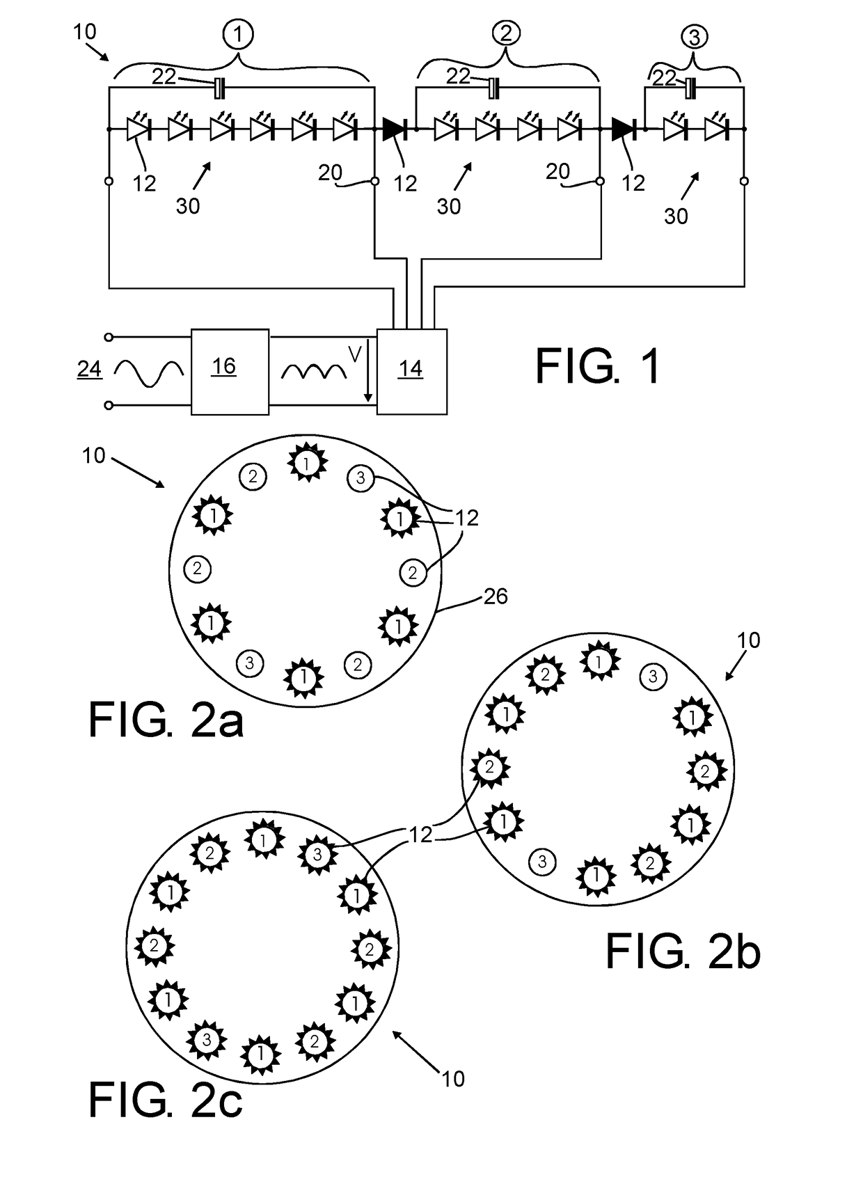
[0041]FIG. 1 shows a circuit diagram of a lighting device 10. The lighting device 10 comprises a plurality of LED elements 12 connected to a step driver circuit 14.
[0042]The LED elements 12 are electrically connected in groups, in the example shown a first group 1, second group 2, and third group 3. In the exemplary circuit shown, all LED elements 12 within each group are electrically connected as LED strings 30, i. e. as series connections of multiple LED elements. In the example of FIG. 1, a first group 1 comprises a string 30 of six LED elements 12, the second group 2 comprises a string 30 of four LED elements 12, and the third group 3 comprises a string 30 of two LED elements 12.
[0043]The strings and thus LED elements 12 from all three groups 1, 2, 3 are electrically connected in series.
[0044]In the preferred embodiment, the individual LED elements 12 are multijunction LED packages, for example with a nominal voltage of 24 V each.
[0045]The groups 1, 2, 3 are connected to the ste...
second embodiment
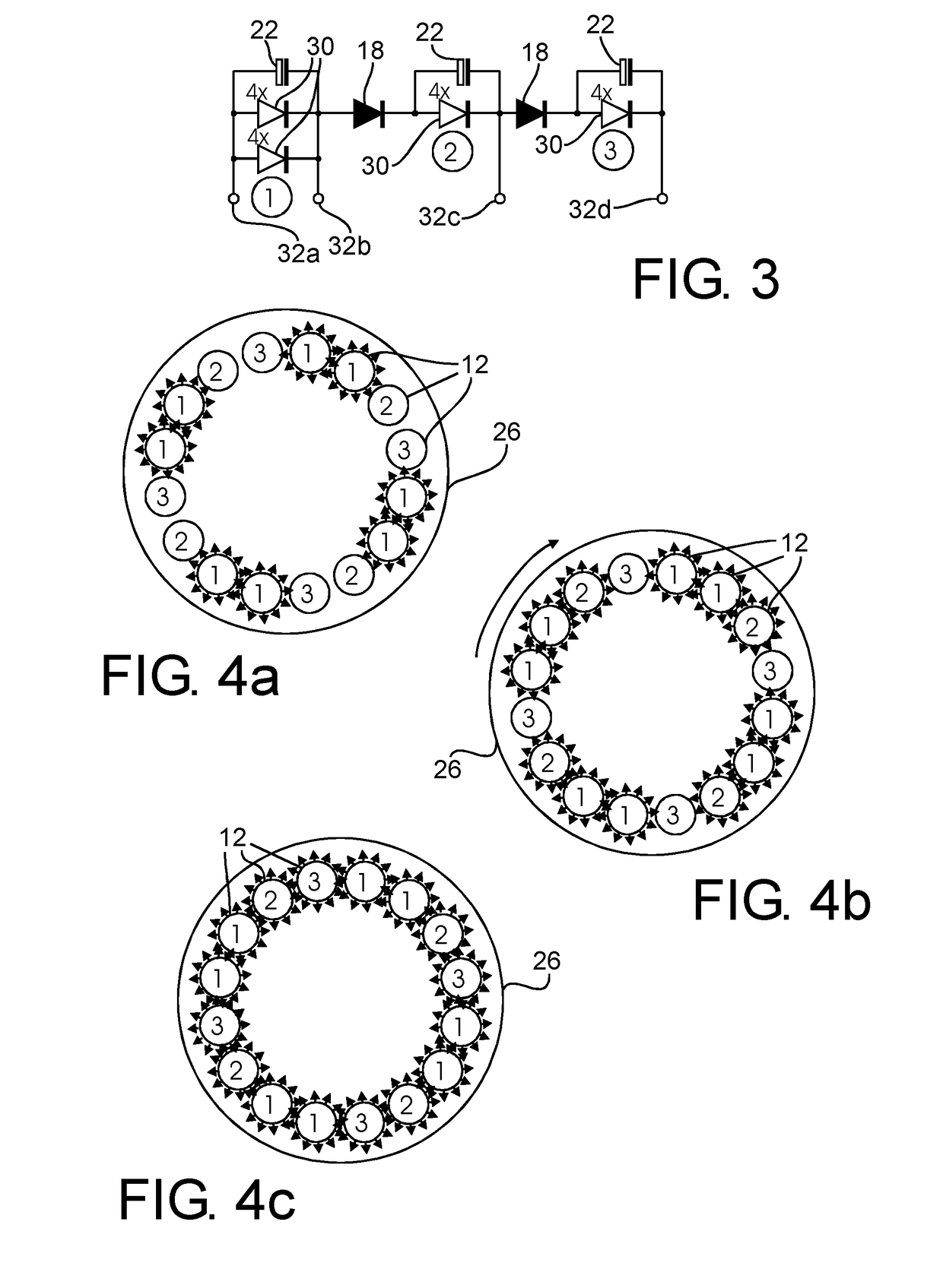
[0064]In the electrical circuit the first group 1 is comprised of two strings 30 connected in parallel. The 16 LED elements each have a nominal voltage of 24 V. Since in the first group 1 strings of four LED elements series are provided, the first threshold is 4×24 V=96 V. The second threshold is 192 V and the third threshold 288 V.
[0065]FIG. 4a shows the arrangement of LED elements from the first group 1, second group 2 and third group 3. Arrows signifying activated LED elements illustrate the optical appearance in FIG. 4a for the first stage, 4b for the second stage and 4c for the third stage.
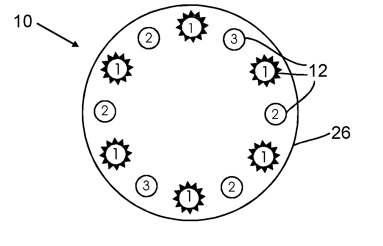
[0066]In this embodiment, the LED elements 12 are arranged in an overall arrangement pattern of a circle on a flat printed circuit board 26. This overall arrangement pattern has a high degree of symmetry, both rotational symmetry and mirror symmetry with regard to multiple axes.
[0067]The LED elements 12 from the first group 1 are evenly distributed over the circular arrangement pattern. The ...
fourth embodiment
[0073]FIGS. 6a-6c show an arrangement of LED elements 12 on a PCB 26 according to a The 11 LED elements 12 with six LED elements 12 in the first group 1, four LED elements 12 in the second group 2 and a single LED element 12 in the third group 3 may be arranged also in the circuit as shown in FIG. 7. For example, each LED element 12 may be an 48 V multijunction LED package.
[0074]The arrangement of LED elements 12 from the first group, as shown in FIGS. 6a-6c, is evenly spaced with two three-element clusters arranged in interleaved manner along a circle.
PUM
 Abstract
Description
Claims
Application Information
 - R&D Engineer
- R&D Manager
- IP Professional
- Industry Leading Data Capabilities
- Powerful AI technology
- Patent DNA Extraction
Browse by: Latest US Patents, China's latest patents, Technical Efficacy Thesaurus, Application Domain, Technology Topic, Popular Technical Reports.
© 2024 PatSnap. All rights reserved.Legal|Privacy policy|Modern Slavery Act Transparency Statement|Sitemap|About US| Contact US: help@patsnap.com