
Set of panel-shaped elements for a composed element

Active Publication Date: 2017-08-10
VÄLINGE INNOVATION AB
View PDF1 Cites 47 Cited by
  • Summary
  • Abstract
  • Description
  • Claims
  • Application Information

AI Technical Summary

Benefits of technology

The patent text describes a set of panels that can be easily assembled into a combined element. This is efficient because it reduces the number of individual components required. The panels are also easy to disassemble, saving time and cost. Additionally, locking the panels without any extra components increases the stability of the combined element. This results in a more secure and tight fit.

Problems solved by technology

The additional connecting piece adds cost to the product, and may make the product instable since a further member is introduced into the product.

Method used


Image

  • Set of panel-shaped elements for a composed element
  • Set of panel-shaped elements for a composed element
  • Set of panel-shaped elements for a composed element

Examples


embodiment 1

[0074]2. The set of panel-shaped elements , wherein

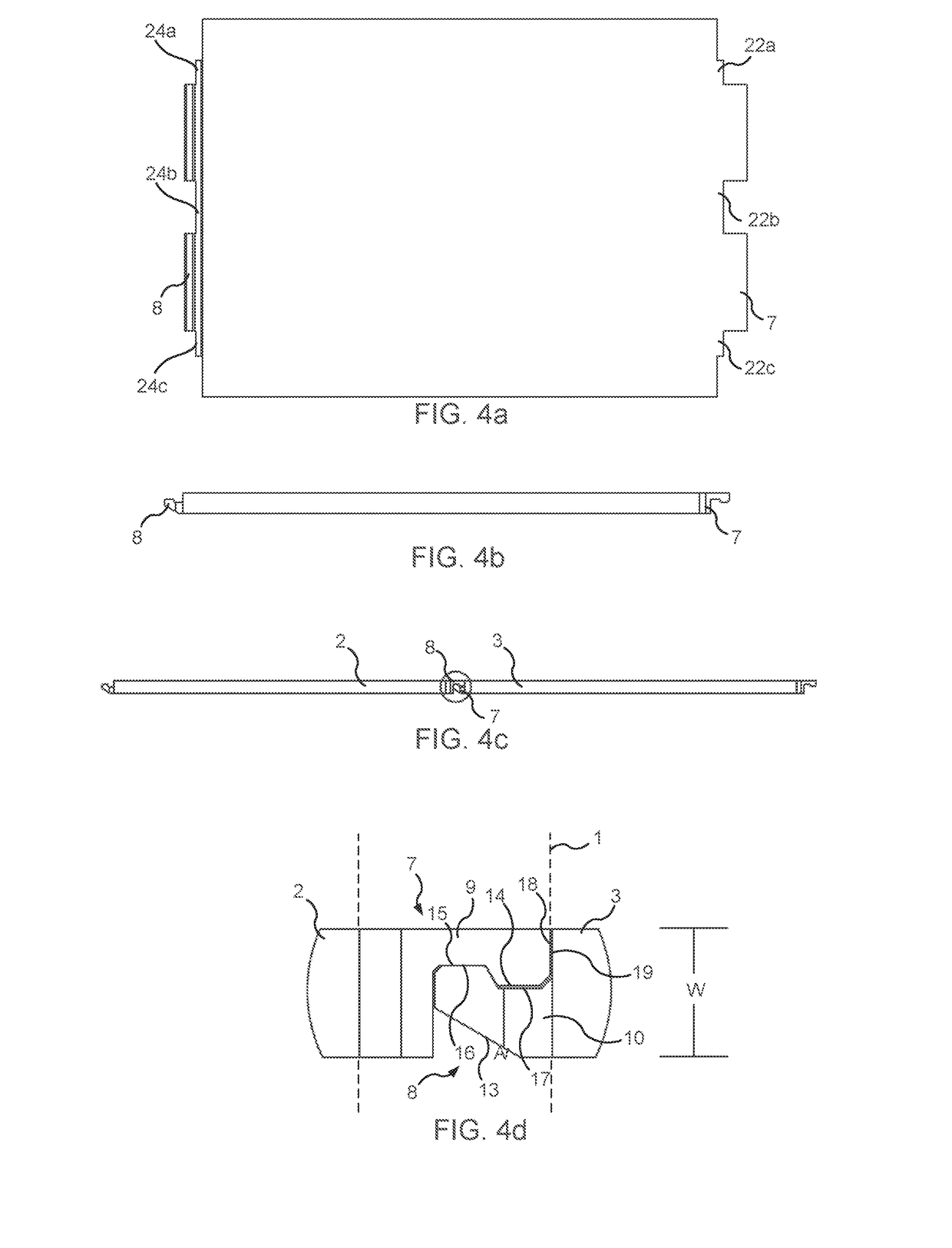
[0075]each of the first profiled portion and the second profiled portion forms a tongue with a locking member sized and configured for mating engagement with the other of the first and the second profiled portion, wherein

[0076]each locking member has a non-flat shape in a longitudinal direction of the second panel-shaped element and the third panel-shaped element, respectively, and

[0077]the locking member of the second panel-shaped element and the locking member of the third panel-shaped element have complementary non-flat shapes and face in opposite directions when received in the recess.

[0078]3. The set of panel-shaped elements according to any of the previous embodiments, wherein a lower surface of second profiled portion is angled at a non-zero angle relative a longitudinal direction of the third panel-shaped element for angled engagement of the second profiled portion with the first profiled portion when the set of panel-shaped...

embodiment 4

[0083]5. The set of panel-shaped elements , wherein the tip portion of the first profiled portion comprises an end surface facing in the longitudinal direction of the second panel, and the third panel comprises an end surface at the base of the second profiled portion, wherein the end surface of the tip portion of the first profiled portion is configured to abut the end surface of the third panel at the base of the second profiled portion.

embodiment 5

[0084]6. The set of panel-shaped elements , wherein

[0085]in a first position for assembling the set of panel-shaped elements a top end of the end surface of the tip portion of the first profiled portion abuts the end surface of the third panel at the base portion of the second profiled portion, and the base portion of the first profiled portion is separated from the tip portion of the second profiled portion; and

[0086]the third panel is configured for angled motion from the first position to a second position, wherein the end surface of the tip portion of the first profiled portion abuts the end surface of the third panel at the base of the second profiled portion, and the base portion of the first profiled portion abuts the tip portion of the second profiled portion.


PUM

PropertyMeasurementUnit
Angleaaaaaaaaaa
Widthaaaaaaaaaa

Abstract

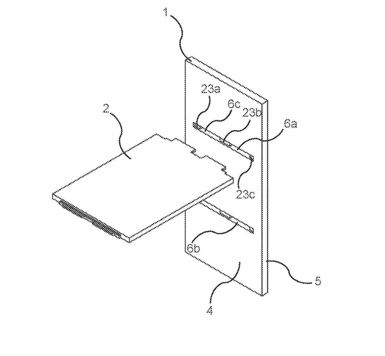
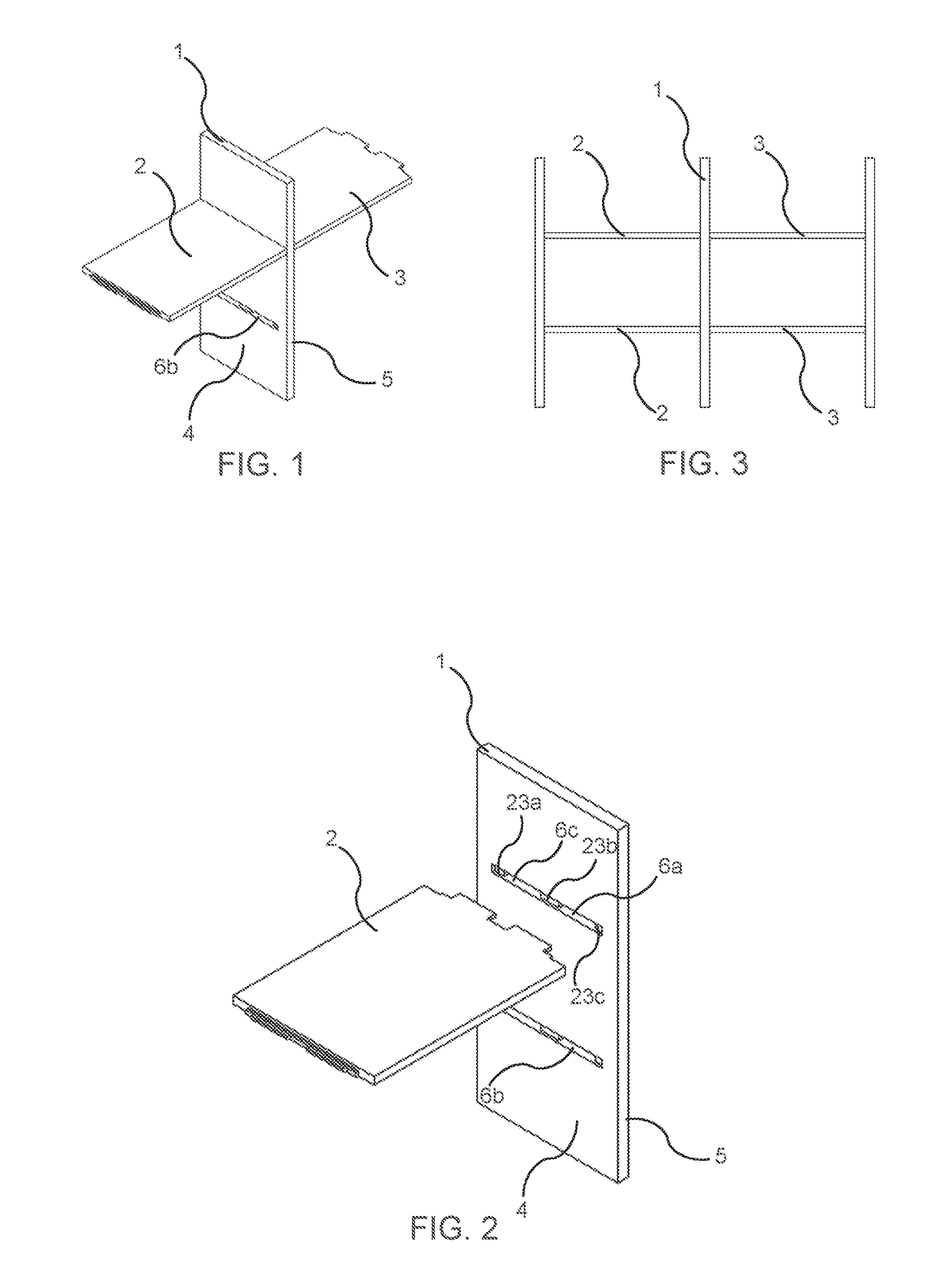
A set of panel-shaped elements includes a first panel-shaped element, a second panel-shaped element, and a third panel-shaped element. The first panel-shaped element includes at least one recess that extends through the first panel-shaped element from a first side to a second side. The second panel-shaped element includes a first profiled portion, which is configured to extend into the recess from the first side of the first panel-shaped element. The third panel-shaped element includes a second profiled portion, which is configured to extend into the recess from the second side of the first panel-shaped element and for locking engagement with the first profiled portion. The set of panel-shaped elements can be assembled using a method where the third element is moved into locking engagement with the first and second elements.

Description

CROSS REFERENCE TO RELATED APPLICATIONS[0001]The present application claims the benefit of Swedish Application No. 1650158-7, filed on Feb. 9, 2016. The entire contents of Swedish Application No. 1650158-7 are hereby incorporated herein by reference in their entirety.FIELD OF THE INVENTION[0002]Embodiments of the present invention relate to a set of panel-shaped elements that can be assembled to a composed element. More particularly, the set of panel-shaped elements comprises a first panel-shaped element, a second panel-shaped element, and a third panel-shaped element. The second panel-shaped element and the third panel-shaped element comprise locking members that can be engaged in locking engagement within a recess of the first panel-shaped element such that all three panel-shaped elements may be locked together. According to an embodiment of a method of the invention, the set of panel-shaped elements can be assembled by moving the third panel-shaped element into locking engagement...

Claims


Application Information

Patent Timeline
IPC IPC(8): F16B5/00F16B12/12A47B3/06F16B12/46A47B88/90A47B47/00
CPCF16B5/008A47B88/941A47B47/0075F16B2012/466F16B12/46F16B12/125A47B3/06A47B47/042A47B2230/0081
Inventor BOO, CHRISTIAN
Owner VÄLINGE INNOVATION AB
Learn More