Simple and Robust Implosion of ICF Targets

a target and implosion technology, applied in the field of simple and robust implosion of icf targets, can solve the problems of high temperature and densities required for fusion ignition that may require a substantial amount of energy, complex design construction and operation, and sensitive to imperfections in the manufacturing of target parts, so as to reduce radiation losses, suppress fluctuations and non-uniformities, effect of reducing radiation losses

Active Publication Date: 2017-08-10
INNOVEN ENERGY
View PDF4 Cites 5 Cited by
  • Summary
  • Abstract
  • Description
  • Claims
  • Application Information

AI Technical Summary

Benefits of technology

[0009]In some embodiments, A method of imploding an Inertial Confinement Fusion (ICF) target may include directing laser energy into a hohlraum, where a target is disposed within the hohlraum that includes an ablator layer, a shell disposed within the ablator layer, and a fuel region disposed within the shell. The method may also include ablating the ablator layer in response to the laser energy being directed into the hohlraum, and generating a single shockwave that is driven inward through the ablator layer. The method may further include impulsively accelerating the shell inward when hit by the single shockwave, and compressing the fuel region by the inward acceleration of the shell. The laser energy may include a square pulse. The method may also include suppressing fluctuations and non-uniformities in a density and pressure profile within the fuel region. The fluctuations and non-uniformities may be su...

Problems solved by technology

Production of the very high temperatures and densities required for fusion ignition may require a substantial amount of energy.
These designs are often complex in their construction and operation.
They are also sensitive to imperfections in the target's manufacturing, as well as any non-uniformity in the delivery of energy to the target from the drive mechanism.
Imperfection and non-uniformity can lead to asymmetry in the target's implosion, which may potentially reduce the densities and temperatures achieved below the threshold required for ignition.
Furthermore, successful operation of these complex desi...

Method used


Image

  • Simple and Robust Implosion of ICF Targets
  • Simple and Robust Implosion of ICF Targets
  • Simple and Robust Implosion of ICF Targets

Examples


Embodiment Construction

[0019]The term “Z” may refer to the atomic number of an element, i.e. the number of protons in the nucleus. The term “A” may refer to the atomic mass number of an element, i.e. the number of protons and neutrons in the nucleus.

[0020]The term “approximately” includes a given value plus / minus 15%. For example, the phrase “approximately 10 units” is intended to encompass a range of 8.5 units to 11.5 units.

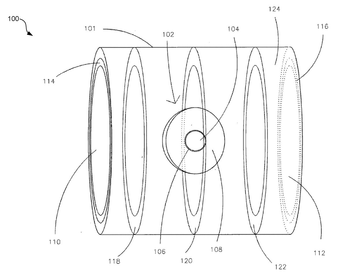
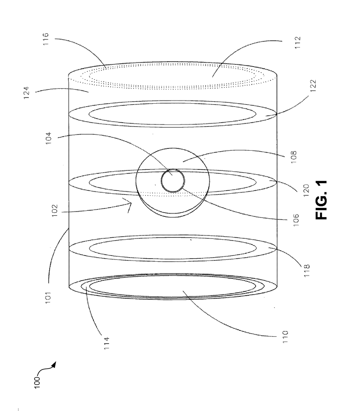
[0021]The term “isentropic drive mechanism” may refer to a drive mechanism that is designed or utilized to compress material (such as fusion fuel) in an isentropic manner. “Isentropic” means compressing material while minimizing the total entropy increase (heating) of the material. Isentropic compression is therefore the most efficient way to compress material. When imploding a sphere or shell of material, such as an ICF target, isentropic compression requires that the drive mechanism deliver pressure to the material in a specific way over the entire duration of the compression, utili...


PUM


Abstract

A method of imploding an Inertial Confinement Fusion (ICF) target may include directing laser energy into a hohlraum, where a target is disposed within the hohlraum that includes an ablator layer, a shell disposed within the ablator layer, and a fuel region disposed within the shell. The method may also include ablating the ablator layer in response to the laser energy being directed into the hohlraum, and generating a single shockwave that is driven inward through the ablator layer. The method may further include impulsively accelerating the shell inward when hit by the single shockwave, and compressing the fuel region by the inward acceleration of the shell.

Description

CROSS-REFERENCES TO RELATED APPLICATIONS[0001]This application claims the benefit of U.S. Provisional Application No. 62 / 388,312 filed on Jan. 22, 2016, which is incorporated herein by reference.BACKGROUND[0002]Nuclear fusion by inertial confinement, Inertial Confinement Fusion (“ICF”), utilizes nuclear fusion reactions to produce energy. In most types of ICF systems, an external drive mechanism, such as a laser, delivers energy to a target containing nuclear fusion fuel. The target is designed to use this energy to compress, heat and ignite the fusion fuel within the target. If a sufficient amount of fuel is compressed sufficiently and heated sufficiently, a self-sustaining fusion reaction can occur in which energy produced by fusion reactions continues to heat the fuel. This is generally referred to as “ignition.” The inertia of the compressed fuel can keep it from expanding long enough for significant energy to be produced before expansion of the fuel and the resultant cooling te...

Claims


Application Information

Patent Timeline
IPC IPC(8): G21B1/19G21B1/23G21B1/03
CPCG21B1/19G21B1/23G21B1/03Y02E30/10
Inventor GALLOWAY, CONNOR D.VALYS, ALEXANDER V.HUNTER, JR., ROBERT O.SOWLE, DAVID H.
Owner INNOVEN ENERGY
Why Eureka
Try Eureka