Coil device

a coil and coil technology, applied in the direction of inductance, inductance with magnetic core, basic electric elements, etc., can solve the problems of deterioration of the bonding condition between the electrode and the winding coil, or between the electrode and the magnetic material, so as to enhance the magnetic characteristic of the magnetic part and improve the inductance or so

Active Publication Date: 2017-08-10
TDK CORPARATION
View PDF5 Cites 4 Cited by
  • Summary
  • Abstract
  • Description
  • Claims
  • Application Information

AI Technical Summary

Benefits of technology

[0028]The first magnetic part does not need to cover other part, hence the content of the resin or so can be less than the second magnetic part; on the other hand the content of the magnetic material can be larger. Therefore, in such coil device, the magnetic characteristic of the magnetic part can be enhanced, and thereby the inductance or so can be improved.

Problems solved by technology

However, for the conventional coil device wherein the connecting part is covered with the magnetic material, when the electrode is applied with heat during the reflow or so which is carried out when surface mounting the coil device, the bonding condition between the electrode and the winding coil, or between the electrode and the magnetic material may deteriorate.

Method used


Image

  • Coil device
  • Coil device
  • Coil device

Examples


Embodiment Construction

[0037]Hereinafter, the present invention will be explained based on the embodiment shown in the figure.

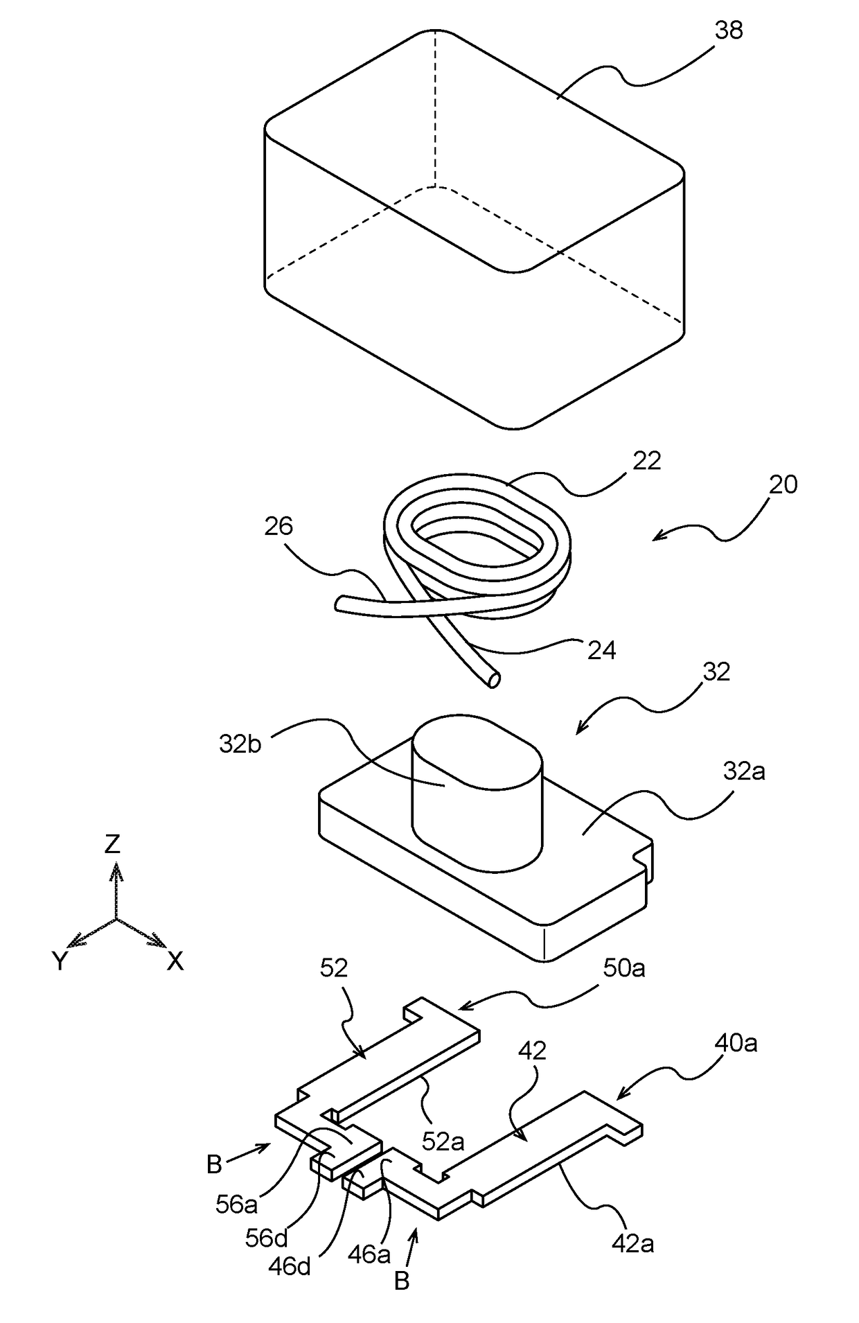
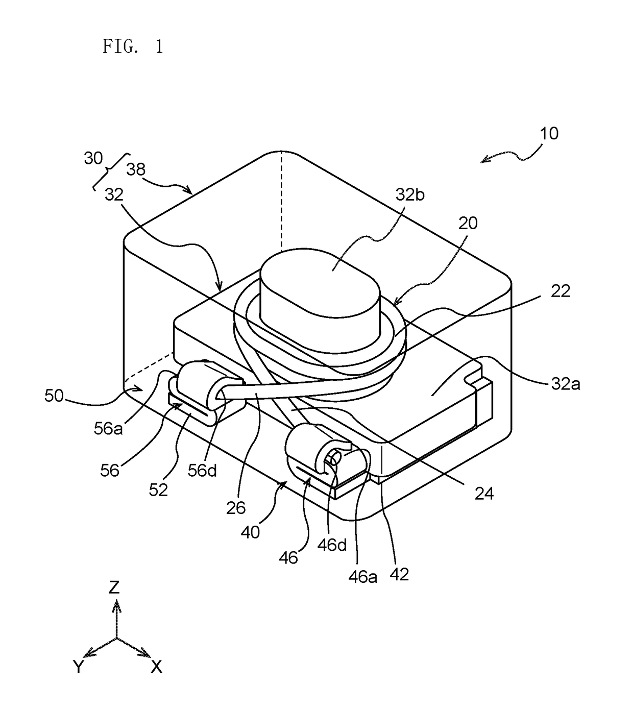
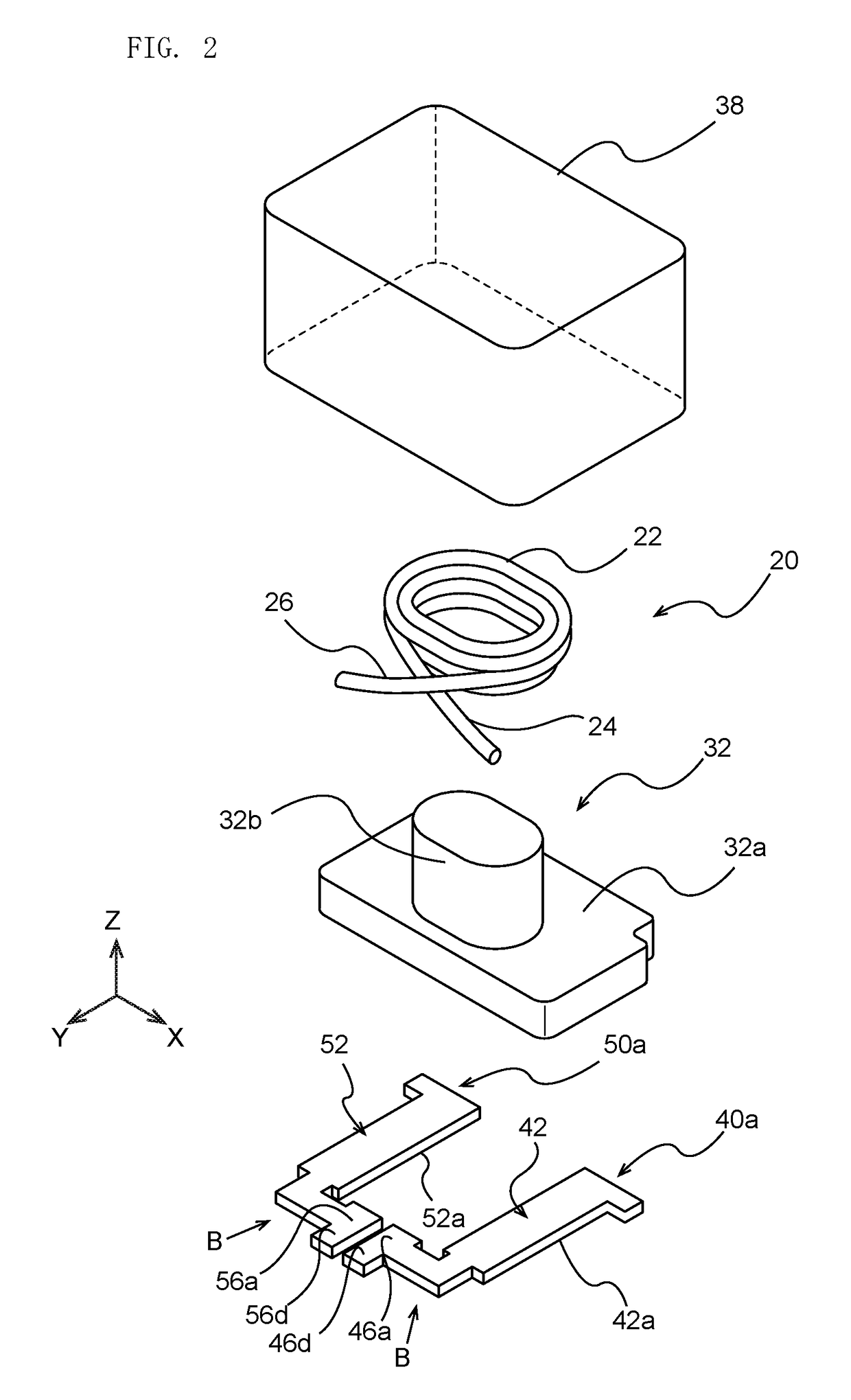
[0038]FIG. 1 is the schematic perspective view of the coil device 10 according to one embodiment of the present invention, and the second magnetic part 38 is shown transparently. The coil device 10 comprises the winding coil 20, the magnetic part 30, and a pair of electrodes 40 and 50.

[0039]As shown in FIG. 1, the coil device 10 has the outer shape of approximately rectangular parallelepiped shape. The outer circumference part of the coil device 10 is constituted by the magnetic part 30 expect for the mounting base faces 42a and 52a of the electrodes 40 and 50 which are exposed at the base face shown in FIG. 4. Therefore, in the actual coil device, the interior structure of the coil device 10 as shown in FIG. 4 cannot be observed from the outside.

[0040]Note that, for the description of the coil device 10, the direction which is perpendicular to the mounting face (the face where the...


PUM

PropertyMeasurementUnit
angleaaaaaaaaaa
conductiveaaaaaaaaaa
circumferenceaaaaaaaaaa

Abstract

A coil device comprising; a winding coil including Cu and having a winding part and an extension line part which is pulled out from said winding part, a pair of electrodes made of a conductive material having, a connecting wire part having a connecting wire face connected with the extension line part and a protective face sandwiching said extension line part with said connecting wire face, and a base part provided with a mounting base face at one of the faces of the base and connected to said connecting wire part, a magnetic part including a magnetic material and covering at least said winding part and said connecting wire part.

Description

BACKGROUND OF THE INVENTION[0001]1. Field of the Invention[0002]The present invention relates to a coil device used as an inductance element or so, and more specifically the present invention relates to the coil device comprising a winding coil covered by a magnetic material.[0003]2. Description of the Related Art[0004]In various electronic and electric devices, many coil devices are installed as the inductance element or a trance. As such coil devices, those comprising the electrodes which can be mounted on the surface using a robot or so, and the winding coil connected to said electrodes being covered by a magnetic part having the magnetic material is proposed (Patent document 1: JP Patent Application Laid Open No. 2003-217941, and Patent document 2: JP Patent Application Laid Open No. H05-315176).SUMMARY OF THE INVENTION[0005]As such coil devices, there is a coil device wherein the connecting part between the electrode and the winding coil covered with the magnetic material (for ...

Claims


Application Information

Patent Timeline
Patent Type & Authority Applications(United States)
IPC IPC(8): H01F27/29H01F27/24H01F27/30H01F27/28
CPCH01F27/29H01F27/306H01F27/24H01F27/2823H01F3/10H01F17/04H01F27/2828H01F27/292H01F2017/048
Inventor TAKAGI, NOBUOKAKIZAKI, KAZUTERUTSUCHIDA, SETU
Owner TDK CORPARATION
Why Eureka
Try Eureka