Intervertebral implant
- Summary
- Abstract
- Description
- Claims
- Application Information
AI Technical Summary
Benefits of technology
Problems solved by technology
Method used
Image

Examples
first embodiment
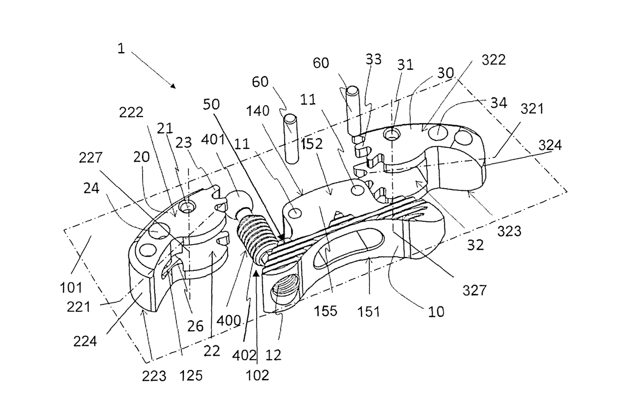
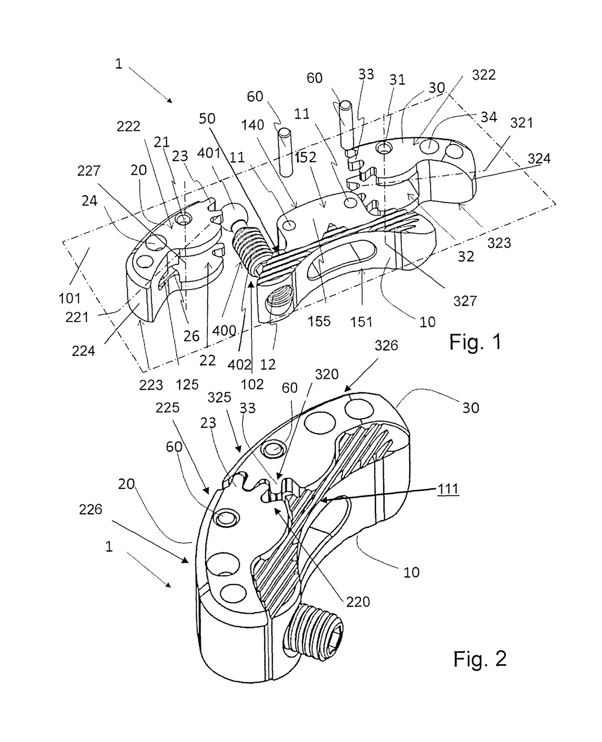
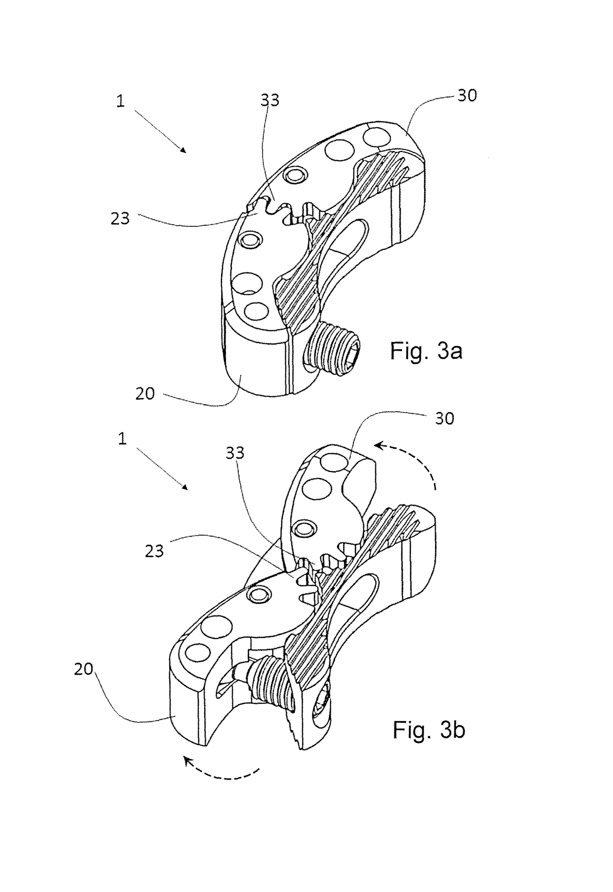
[0143]FIGS. 1 to 5b illustrate a first embodiment the intervertebral implant 1 according to the invention which essentially comprises:[0144]a first elongated implant member 20 with a longitudinal axis 221, an upper surface 222 and a lower surface 223 for apposition to the endplates of two adjacent vertebrae, and with a lateral circumferential surface 224; and[0145]a second elongated implant member 30 with a longitudinal axis 321, an upper surface 322 and a lower surface 323 for apposition to the same endplates and with a lateral circumferential surface 324, wherein the first and second elongated implant members 20, 30 are rotatably coupled to a central body 10 for rotation in a central plane 101 essentially parallel to said upper and lower surfaces.
[0146]Furthermore, said first and second elongated implant members 20, 30 comprise each an inner end portion 225;325 which comprises a circular segment of a toothed wheel 220;320 with gear teeth 23;33 and with an axis of rotation 227;327 ...
third embodiment
[0160]FIGS. 6 and 7 illustrate the intervertebral implant 1 according to the invention, comprising three or more elongated implant members 20, 30, 40, 50, wherein said implant members 20, 30, 40, 50 are rotatably coupled to the central body 10. Furthermore, the circular segment of a toothed wheel 220;320;420;520 of each of said elongated implant members 20, 30, 40, 50 is in engagement with the circular segment of a toothed wheel 220;320;420;520 of two others of said elongated implant members 20, 30, 40, 50.
[0161]Each of the elongated implant members 20, 30, 40, 50 comprises a longitudinal axis 221;321;421;521, an upper surface 222;322;422;522, a lower surface 223;323;423;523 for apposition to the endplates of two adjacent vertebrae and a lateral circumferential surface 224;324;424;524. The elongated implant members 20, 30, 40, 50 are each rotatably coupled to the central body 10 for rotation in the central plane 101. Each of the elongated implant members 20, 30, 40, 50 comprises an ...
fifth embodiment
[0169]FIGS. 10a to 10c show the intervertebral implant 1 according to the present invention. In FIG. 10a, the first elongated implant member 20 and the second elongated implant member 30 are shown in a cut-away view. In this embodiment, the central body 10 comprises a channel 12 into which a worm 13 acting as a driving means 102 is arranged. The worm 13 includes a worm thread 14 which is in engagement with secondary gear teeth 25 of the first elongated implant member 20. Rotation of the worm 13 within the channel 12 will rotate the secondary gear teeth 25, as the worm thread 14 and the secondary gear teeth 25 constitute a worm-gear, and thus the first elongated implant member 20 will be rotated around the respective gear-pin 60. Such as to impart a rotation onto worm 13, a drive 15 is arranged on one end of said worm 13. Access to said drive 15 is made possible through the channel 12, e.g. for a suitable instrument. In the embodiment shown, the drive 15 is configured as hexagonal dr...
PUM
 Abstract
Description
Claims
Application Information
 - Generate Ideas
- Intellectual Property
- Life Sciences
- Materials
- Tech Scout
- Unparalleled Data Quality
- Higher Quality Content
- 60% Fewer Hallucinations
Browse by: Latest US Patents, China's latest patents, Technical Efficacy Thesaurus, Application Domain, Technology Topic, Popular Technical Reports.
© 2025 PatSnap. All rights reserved.Legal|Privacy policy|Modern Slavery Act Transparency Statement|Sitemap|About US| Contact US: help@patsnap.com