Apparatus for Fabricating an Object

Inactive Publication Date: 2017-08-17
LAING OROURKE AUSTRALIA PTY LTD
View PDF18 Cites 32 Cited by
  • Summary
  • Abstract
  • Description
  • Claims
  • Application Information

AI Technical Summary

Problems solved by technology

Whilst casting or moulding often proves reliable, these processes also suffer from a number of drawbacks.
One issue common to many non-standard geometry objects is the presence of ‘undercut’ or ‘over-hanging’ surfaces.
If an object is cast or moulded having such surfaces using a conventional, rigid mould tool, the tool becomes trapped by the undercut surfaces against the object when the molten material solidifies, proving difficult or impossible to remove the mould tool from the object without damaging the object and/or the tool.
However, these tools are typically expensive due to the complexity of the moving tool parts and can require a considerable length of time and/or energy to remove the tool from the object.
However, additive manufacturing techniques also suffer from other drawbacks.
When an object havin

Method used


Image

  • Apparatus for Fabricating an Object
  • Apparatus for Fabricating an Object
  • Apparatus for Fabricating an Object

Examples


Embodiment Construction

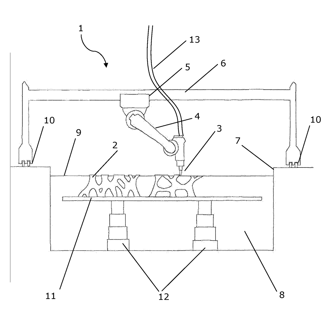
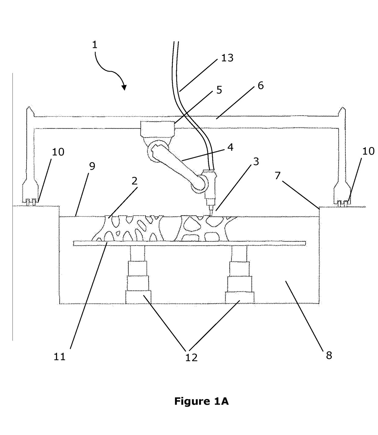
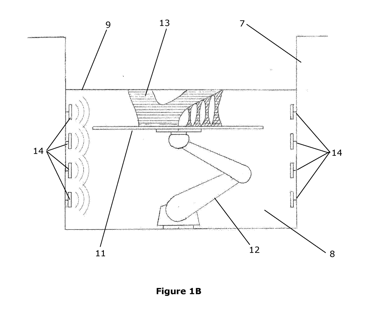
[0027]The present disclosure relates generally to methods and apparatus for fabricating an object using a computer-controlled apparatus, responsive to computer instructions relating to the object geometry. In particular, the disclosure relates to a computer-controlled apparatus for fabricating an object which includes a deposition head in communication with a supply of first material and adapted to expel the first material therefrom, a reservoir which is at least partially filled with a fluid-like second material, and a controller configured to selectively move at least one of the deposition head and at least a portion of the reservoir relative to each other, and selectively operate the deposition head, in order to deposit the first material in specific locations to form an object which corresponds with the object geometry, whereby at least a portion of the object is submerged in the second material.

[0028]The disclosed apparatus and method is useful when fabricating an object which ...


PUM

PropertyMeasurementUnit
Flow rateaaaaaaaaaa
Responsivityaaaaaaaaaa

Abstract

A computer-controlled additive manufacturing apparatus for fabricating an object. The apparatus includes a deposition head for selectively expelling first material therefrom, a reservoir containing a fluid-like second material, and a controller. At least one of the deposition head and at least a portion of the reservoir are movable, and the controller is configured to move at least one of the deposition head and the at least a portion of the reservoir relative to each other, and selectively operate the deposition head to expel the first material therefrom, responsive to computer instructions, thereby progressively depositing the first material in specific locations to fabricate the object having at least a portion thereof submerged in the second material.

Description

TECHNICAL FIELD[0001]The present invention relates generally to fabricating objects and in particular, relates to fabricating an object with a computer-controlled ‘additive manufacturing’ apparatus.BACKGROUND TO THE INVENTION[0002]Objects have been fabricated using a range of different casting or moulding techniques for some time. Casting or moulding generally involves introducing molten material, such as plastic or metal, into a cavity defined by a mould tool. After the material cools and hardens, a solid object is removed from the tool having a corresponding geometry to the cavity.[0003]Whilst casting or moulding often proves reliable, these processes also suffer from a number of drawbacks. For example, as design and engineering has become more sophisticated, the need for non-standard ‘freeform’ geometry objects has increased. One issue common to many non-standard geometry objects is the presence of ‘undercut’ or ‘over-hanging’ surfaces. If an object is cast or moulded having such...

Claims


Application Information

Patent Timeline
IPC IPC(8): B29C67/00B33Y50/02B33Y30/00
CPCB29C67/0088B33Y50/02B33Y30/00B29C67/0055B33Y70/00B29C64/40B29C64/209B29C64/241B29C64/227B29C64/386B29C64/118B29C64/106
Inventor GARDINER, JAMES BRUCEMATTHEW, LEX
Owner LAING OROURKE AUSTRALIA PTY LTD
Why Eureka
Try Eureka