
Powder distribution in additive manufacturing

a technology of additive manufacturing and powder storage, applied in the direction of additive manufacturing processes, manufacturing tools, chemistry apparatus and processes, etc., can solve the problem of affecting the amount of powder storage removed

Active Publication Date: 2015-09-08
ARCAM AB
View PDF100 Cites 126 Cited by
  • Summary
  • Abstract
  • Description
  • Claims
  • Application Information

AI Technical Summary

Benefits of technology

[0017]An advantage of the present invention is that the amount of powder provided on the powder table may be more precisely defined and the repeatability is improved compared to state of the art technique.
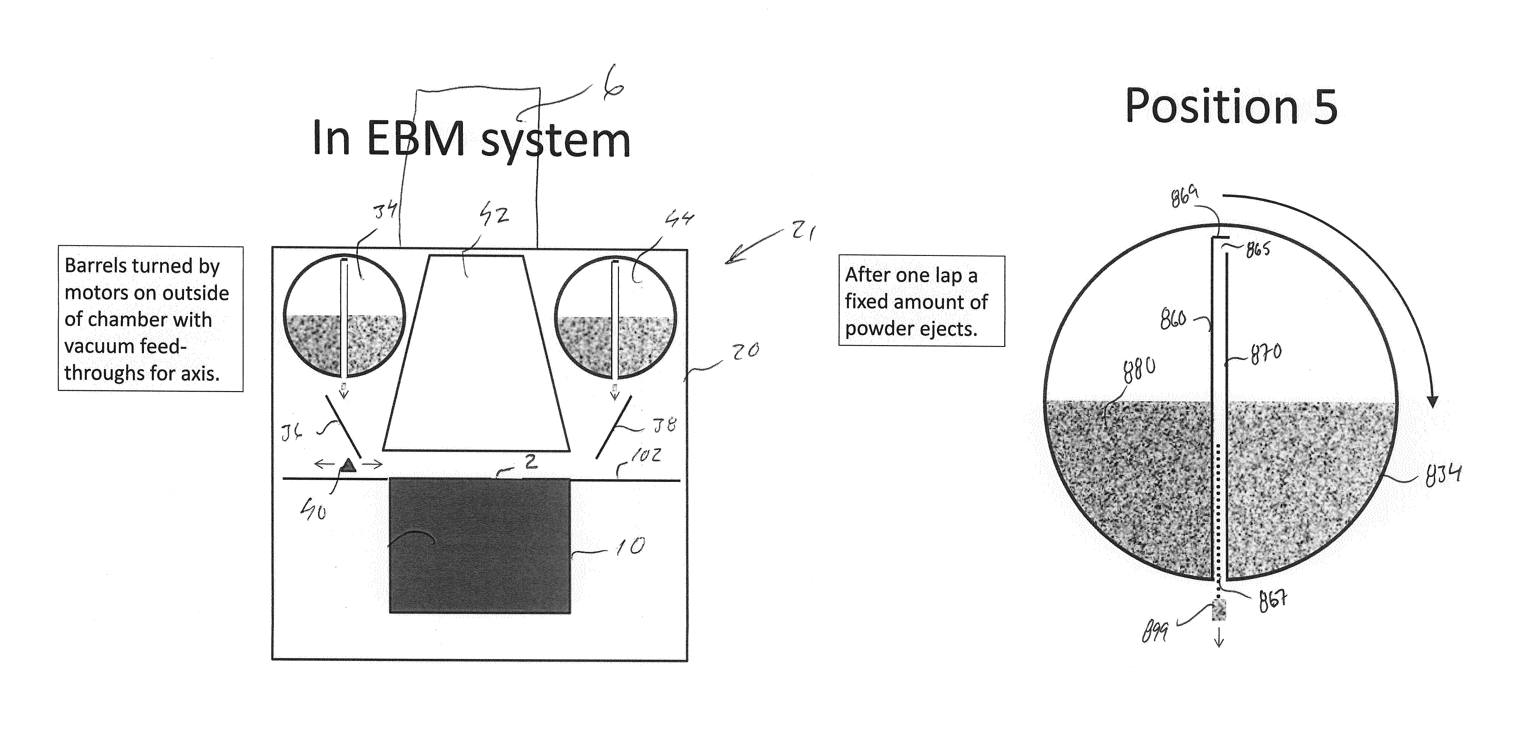
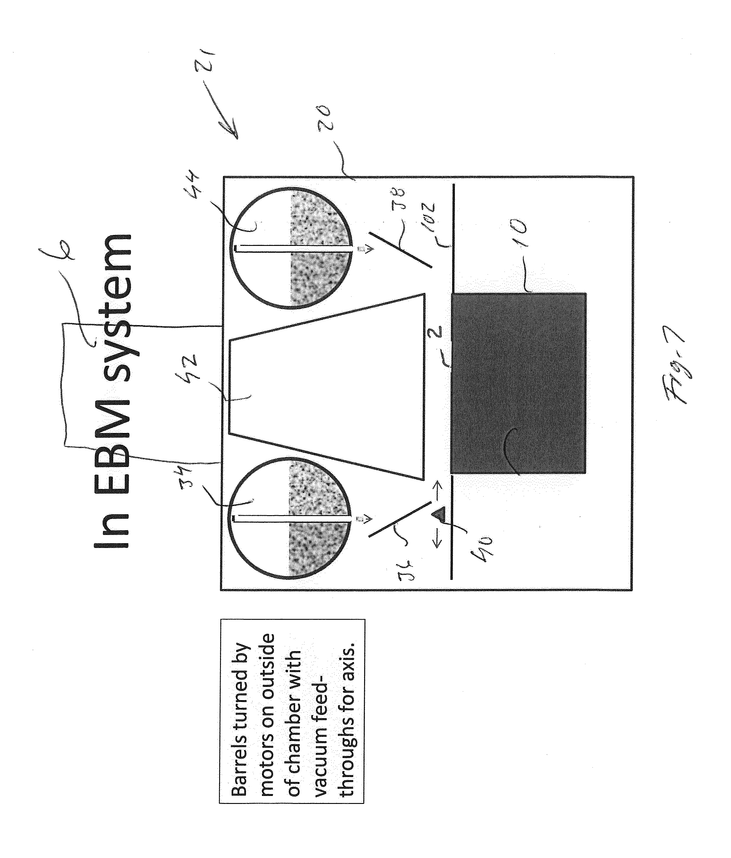
[0036]An advantage of said embodiment is that the powder size and position of the powder container is less critical. In a second aspect of the invention it is provided an additive manufacturing apparatus for forming a three-dimensional article through successive fusion of parts of at least one layer of a powder bed provide on a work table, which parts corresponds to successive cross sections of the three-dimensional article. Said apparatus comprises at least one rotatable powder container above said work table. Said powder container comprising at least one exit for providing powder to a powder table arranged beside said worktable. At least one opening inside said container is spatially separated from and connected to said at least one exit. A distributor is provided for distributing at least a part of said fixed amount of powder from said powder table to said work table for forming at least a part of a layer of said powder bed.

Problems solved by technology

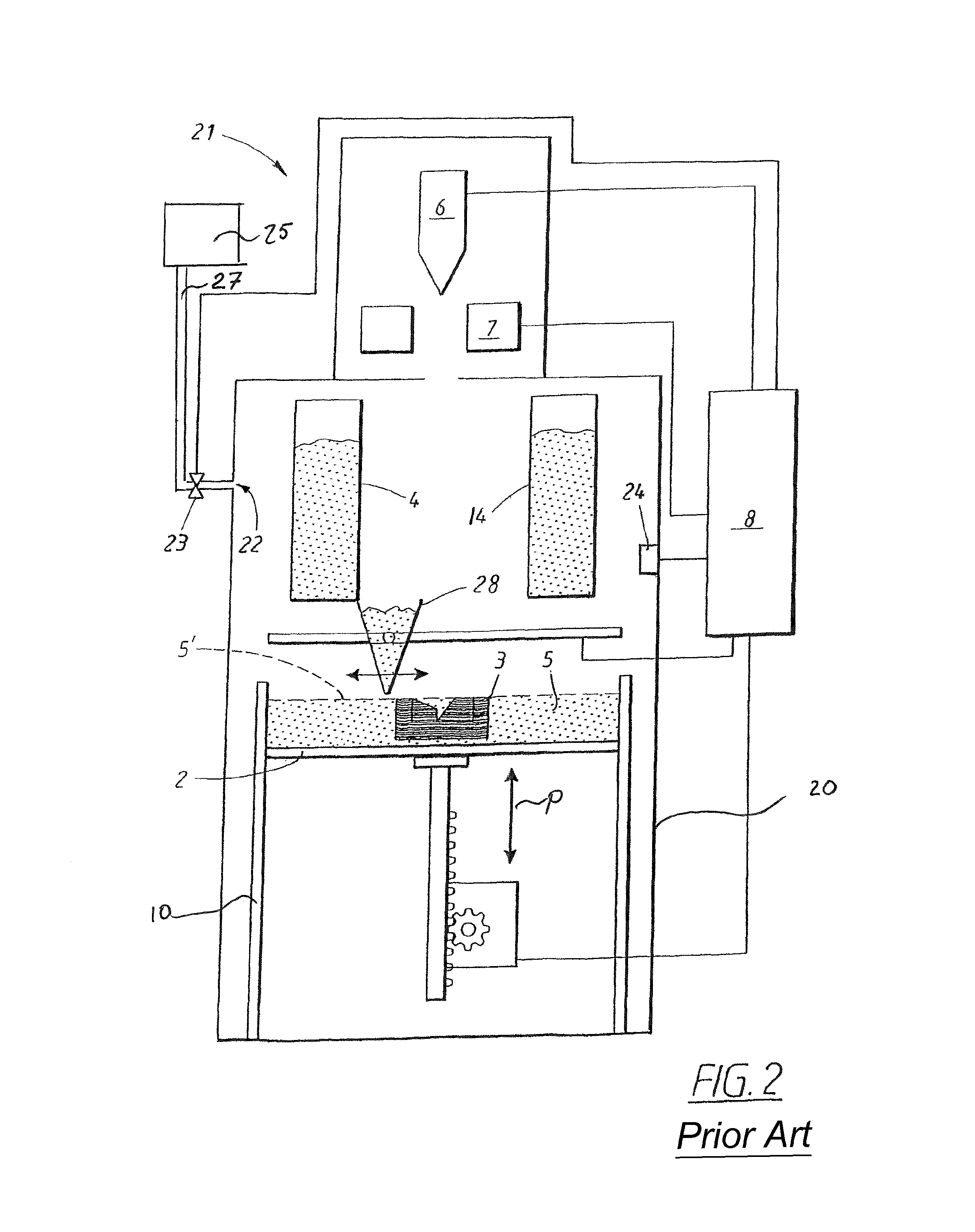
A problem with said solution is that the powder quality, i.e., the powder humidity, powder composition, powder size and powder amount in the powder storage etc. may affect the amount removed from the powder storage.

Method used


Image

  • Powder distribution in additive manufacturing
  • Powder distribution in additive manufacturing
  • Powder distribution in additive manufacturing

Examples


Embodiment Construction

[0059]To facilitate the understanding of this invention, a number of terms are defined below. Terms defined herein have meanings as commonly understood by a person of ordinary skill in the areas relevant to the present invention. Terms such as “a”, “an” and “the” are not intended to refer to only a singular entity, but include the general class of which a specific example may be used for illustration. The terminology herein is used to describe specific embodiments of the invention, but their usage does not delimit the invention, except as outlined in the claims.

[0060]The term “three-dimensional structures” and the like as used herein refer generally to intended or actually fabricated three-dimensional configurations (e.g. of structural material or materials) that are intended to be used for a particular purpose. Such structures, etc. may, for example, be designed with the aid of a three-dimensional CAD system.

[0061]The term “electron beam” as used herein in various embodiments refer...


PUM

PropertyMeasurementUnit
pressureaaaaaaaaaa
accelerating voltageaaaaaaaaaa
rotational anglesaaaaaaaaaa

Abstract

An additive manufacturing method for forming a three-dimensional article through successive fusion of parts of at least one layer of a powder bed provided on a work table. Providing at least one rotatable powder container above said work table, said powder container comprising at least one exit for providing powder to a powder table arranged beside said work table, at least one opening inside said container is spatially separated from and connected to said at least one exit. Ejecting a fixed amount of powder from said powder container during at least one predetermined segment of rotational angles of said powder container, from the exit of said powder container onto said powder table, wherein said fixed amount is determined by the shape and size of the at least one opening inside said container. Distributing said powder onto said work table with a powder distributor.

Description

CROSS REFERENCE TO RELATED APPLICATIONS[0001]This application is a National Stage Application, filed under 35 U.S.C. §371, of International Application No. PCT / EP2012 / 058733, filed May 11, 2012, the contents of which are hereby incorporated by reference in their entirety.BACKGROUND[0002]1. Related Field[0003]The present invention relates to a method and apparatus for additive manufacturing according to the preamble of the claims provided herein.[0004]2. Description of Related Art[0005]Freeform fabrication or additive manufacturing is a method for forming three-dimensional articles through successive fusion of chosen parts of powder layers applied to a worktable.[0006]An additive manufacturing apparatus may comprise a work table on which said three-dimensional article is to be formed, a powder dispenser, arranged to lay down a thin layer of powder on the work table for the formation of a powder bed, an energy beam for delivering energy to the powder whereby fusion of the powder takes...

Claims


Application Information

Patent Timeline
Patent Type & Authority Patents(United States)
IPC IPC(8): B29C67/00B22F3/105B22F3/00B01J6/00B33Y10/00B33Y30/00
CPCB01J6/005B22F3/004B22F3/1055B29C67/0051B29C67/0077B29C67/0085B22F2003/1056B33Y10/00B33Y30/00B29C64/153B29C64/336B29C64/295Y02P10/25B22F10/28B22F12/52B22F12/37B22F10/10B22F12/58B22F12/13B22F12/55B22F10/34
Inventor LJUNGBLAD, ULRIC
Owner ARCAM AB
Learn More