Methods for manufacturing components from articles formed by additive-manufacturing processes

Active Publication Date: 2013-03-21
HONEYWELL INT INC
View PDF0 Cites 126 Cited by
  • Summary
  • Abstract
  • Description
  • Claims
  • Application Information

AI Technical Summary

Benefits of technology

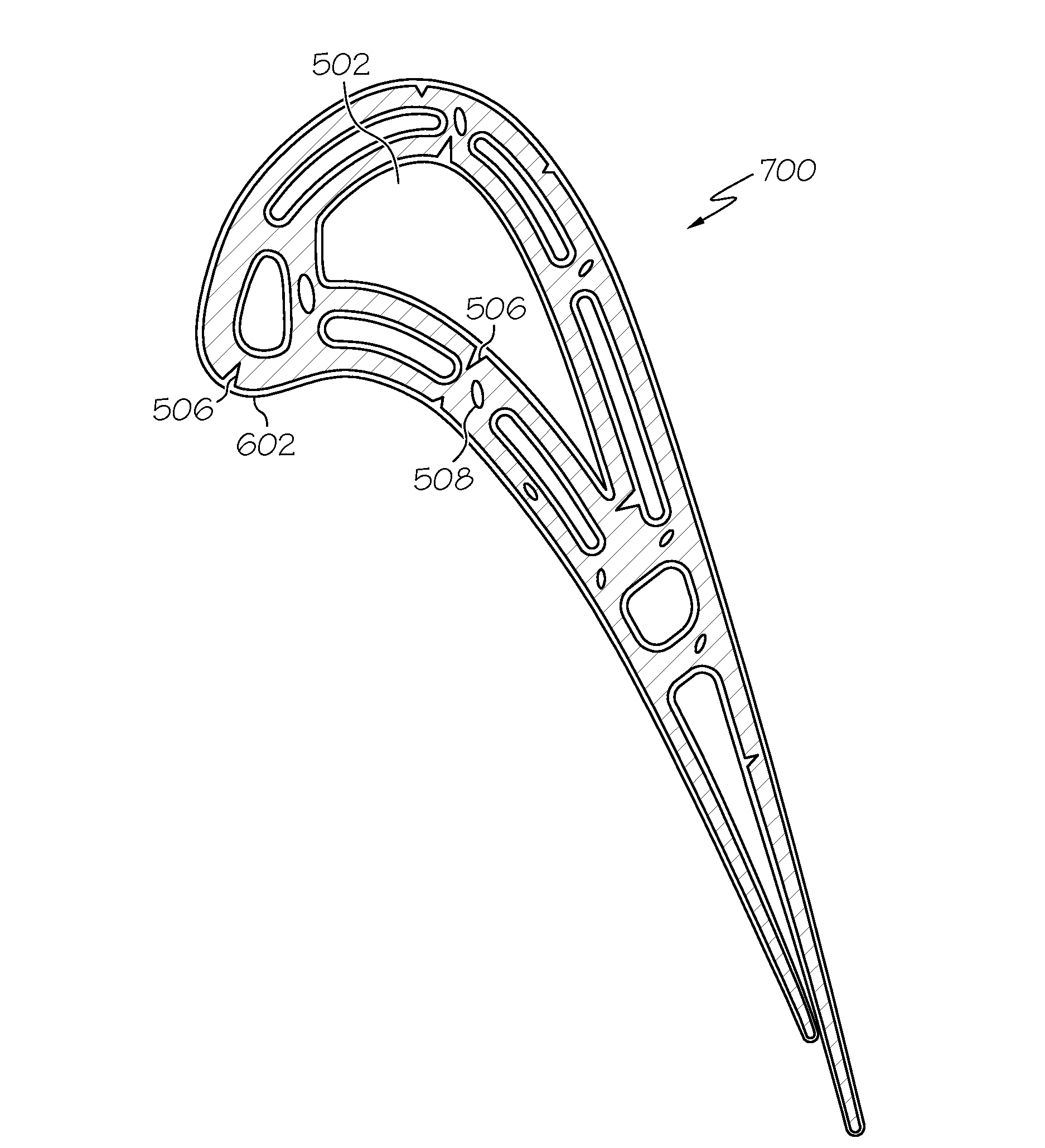
[0046]FIG. 6 illustrates a portion of the first intermediate article of FIG. 5, including a portion of the material substrate 510 and a representative rough internal passage surface thereof The material substrate 510 also includes an exemplary internal defect 508. As noted above, for components with high surface roughness, the structural integrity and mechanical properties thereof may be compromised. In addition, for those components with high surface roughness also needing a reduction in internal and surface-connected defects, surface-connected defects thereof may not be successfully bridged and covered by an encapsulation layer to conve

Problems solved by technology

Components with relatively complex three-dimensional (3D) geometries raise difficult fabrication issues.
Such conventional methods are not only expensive and have long lead-times, but may additionally have low yields.
Development time and cost for certain components may also be magnified because such components generally require several iterations, including iterations as a result of intentional design decisions.
Cracks may develop at these interfaces or cut through or across deposit layers dues to stresses inherent with the additive manufacturing process and/or the metallurgy of the build material.
However, for components with significant surface roughness, the encapsulation process may not sufficiently bridge and cover the surface-connected defects.
Surface roughness may also be objectionable to customer perception of quality and may interfere with the functionality of the component.
For example, excessive surface roughness may restrict or impede airflow, collect debris, act as a stress riser, and otherwise detract from the component design.
Unfortunately

Method used


Image

  • Methods for manufacturing components from articles formed by additive-manufacturing processes
  • Methods for manufacturing components from articles formed by additive-manufacturing processes
  • Methods for manufacturing components from articles formed by additive-manufacturing processes

Examples


example

[0067]The following example is provided for illustration purposes only, and is not meant to limit the various embodiments of the present invention in any way. In the following example, an aluminide diffusion coating is formed on an internal surface of an exemplary turbine article (an HP turbine blade) formed from a DMLS additive manufacturing process using high temperature, high strength nickel-based superalloys (MM247 and IN738), in accordance with exemplary embodiments. FIGS. 14-17 are images of the exemplary turbine article or portions thereof As shown in FIG. 14, the turbine article has both internal passage surface roughness and defects (the internal surface referred to by reference element 304a) and external surface (304b) roughness and defects. FIG. 15 is an image of the turbine article of FIG. 14 after encapsulation and HIP processing. The external surface 304b was conventionally polished prior to encapsulation and HIP processing to eliminate the external surface roughness a...


PUM

PropertyMeasurementUnit
Surface roughnessaaaaaaaaaa

Abstract

A method is provided for manufacturing a component. The method includes forming a diffusion coating on a first intermediate article formed by an additive manufacturing process. The diffusion coating is removed from the first intermediate article forming a second intermediate article having at least one enhanced surface. The diffusion coating is formed by applying a layer of coating material on at least one surface of the first intermediate article and diffusion heat treating the first intermediate article and the layer. The diffusion coating comprises a surface additive layer and a diffusion layer below the surface additive layer. The formation of the diffusion coating and removal thereof may be repeated at least once.

Description

TECHNICAL FIELD[0001]The present invention generally relates to methods for manufacturing components, and more particularly relates to methods for manufacturing components from articles formed by additive-manufacturing processes.BACKGROUND[0002]Components with relatively complex three-dimensional (3D) geometries raise difficult fabrication issues. Conventional fabrication techniques include forging, casting, and / or machining. Such conventional methods are not only expensive and have long lead-times, but may additionally have low yields. Development time and cost for certain components may also be magnified because such components generally require several iterations, including iterations as a result of intentional design decisions.[0003]Additive manufacturing (AM) processes (including those which form “cores” for subsequent conventional casting) have been developed to fabricate components having relatively complex three dimensional geometries, including components with internal surf...

Claims


Application Information

Patent Timeline
IPC IPC(8): B05D3/12B05D3/02
CPCB22F3/1055B22F3/15B22F3/24B22F5/04F05D2230/31B29C67/0051C23C10/60C23C26/00B22F7/06B33Y30/00B33Y80/00B33Y70/00Y02P10/25B22F10/62B22F12/49B22F10/66B22F10/25B22F12/63B22F10/36B22F10/28B22F10/64B33Y40/20
Inventor SZUROMI, ANDYRYAN, DANIELGODFREY, DONALD G.MORRIS, MARK C.
Owner HONEYWELL INT INC
Why Eureka
Try Eureka