
Activation control device for occupant protection device

a technology of occupant protection device and activation control, which is applied in the direction of pedestrian/occupant safety arrangement, vehicle safety belt, vehicle components, etc., can solve the problems of difficulty in advancing the activation timing collision determination threshold cannot be decreased, delay in activation of the occupant protection device, etc., and achieve the effect of reducing the repair cost after the collision

Inactive Publication Date: 2017-08-17
TOYOTA JIDOSHA KK
View PDF0 Cites 7 Cited by
  • Summary
  • Abstract
  • Description
  • Claims
  • Application Information

AI Technical Summary

Benefits of technology

The patent text describes a system that allows for the accurate detection and identification of different types of collisions in a vehicle. By doing so, the system ensures that only the appropriate occupant protection devices are activated, such as airbags or seatbelt pretensioners, which can help to decrease repair costs after a collision. Additionally, the system helps to prevent the transmission of force from the collision to the cabin via the side members, which can help to reduce the likelihood of injury to occupants during a pole collision.

Problems solved by technology

As a result, the activation of the occupant protection devices may be delayed when the pole collision occurs.
Thus, the prior-art device cannot clearly distinguish the pole collision and the head-on collision at a low velocity from each other, and hence the collision determination threshold cannot be decreased when the pole collision occurs.
As a result, it is difficult to advance the activation timing of the occupant protection devices.

Method used


Image

  • Activation control device for occupant protection device
  • Activation control device for occupant protection device
  • Activation control device for occupant protection device

Examples


second embodiment

[0165]A description is now given of the present control device according to a second embodiment of the present invention (hereinafter also referred to as “second device”). The second device is different from the first device only in that the occupant protection devices to be activated are changed in correspondence to the determined collision form. A description is now given of this difference.

[0166](Overview of Activation Control Logic)

[0167]As illustrated in FIG. 12, an activation control logic for the occupant protection devices according to the second device is different from the activation control logic according to the first device only in that the second device includes two OR circuit units 200A and 200B in place of the OR circuit unit 100 of the first device.

[0168]The OR circuit unit 200A is configured to receive the output signals from the AND circuit units 53, 63, 73, 83 and 93. Thus, when one of the output signals of the AND circuit units 53, 63, 73, 83 and 93 becomes the ...

third embodiment

[0174]A description is now given of the present control device (hereinafter also referred to as “third device”) according to a third embodiment of the present invention. The third device is different from the first device only in that the collision determination is carried out based on a comparison of magnitudes between the front / rear acceleration Gx and the collision determination threshold, and that the velocity decrease amount Vx is not used for the collision determination. A description is now given of this difference.

[0175](Overview of Activation Control Logic of Third Device)

[0176]As illustrated in FIG. 13, an activation control logic for the occupant protection devices according to the third device is different from the activation control logic according to the first device only in that the activation control logic according to the third device does not include the velocity decrease amount calculation unit 50 illustrated in FIG. 5, includes threshold generation units 51A, 61A...

fourth embodiment

[0191]A description is now given of the present control device (hereinafter also referred to as “fourth device”) according to a fourth embodiment of the present invention. The fourth device is different from the third device only in that, when the collision form is the pole collision, the occupant protection devices are activated at a time point at which the collision form is determined to be the pole collision without performing the comparison of the magnitudes between the front / rear acceleration Gx and the collision determination threshold. A description is now given of this difference.

[0192](Overview of Activation Control Logic of Fourth Device)

[0193]As illustrated in FIG. 17, an activation control logic for the occupant protection devices according to the fourth device is different from the activation control logic according to the third device only in that the “pole collision threshold generation unit 61A and comparison unit 62A” are omitted from the control logic of the third ...


PUM


Abstract

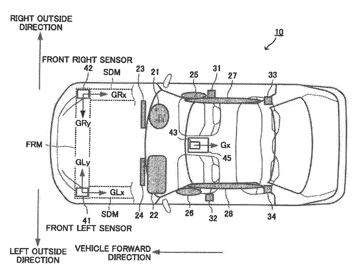
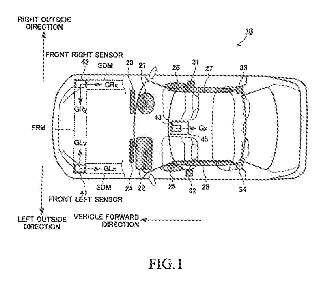
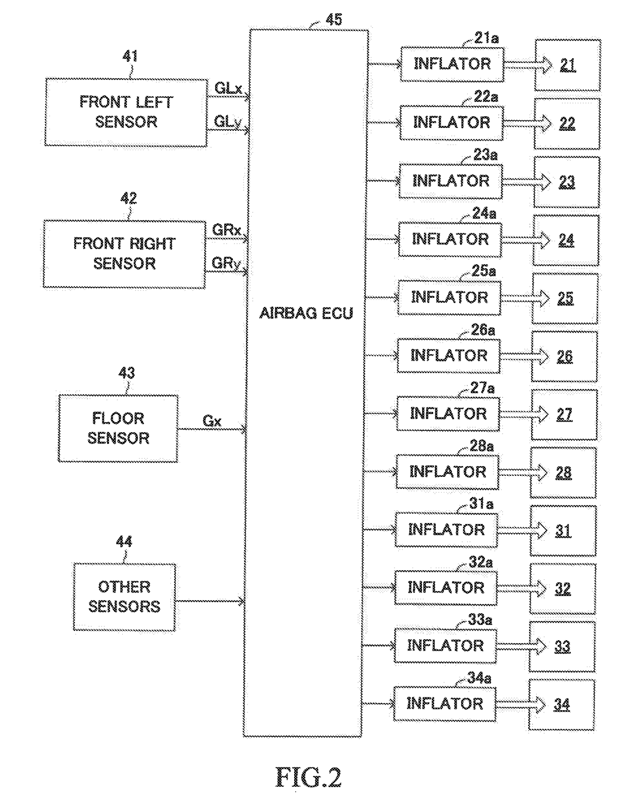
An activation control device for at least one occupant protection device is applied to a vehicle including occupant protection devices. The activation control device includes a front left sensor, a front right sensor and an activation control unit. The front left sensor is configured to detect an acceleration in a vehicle widthwise direction, and the front right sensor is configured to detect an acceleration in the vehicle widthwise direction. The activation control unit is configured to calculate a movement amount of the front left sensor in the vehicle widthwise direction based on GLy, calculate a movement amount of the front right sensor in the vehicle widthwise direction based on GRy, and determine to which region out of regions each defined in advance for each collision form a point defined by those movement amounts belongs, thereby specifying a collision form.

Description

TECHNICAL FIELD[0001]The present invention relates to an activation control device for at least one occupant protection device, which is configured to control activation of at least one“occupant protection device, e.g., an airbag device and a seatbelt retractor” configured to protect occupants in a vehicle when the vehicle collides with an obstacle.BACKGROUND ART[0002]As illustrated in FIG. 21, one of the “activation control devices for at least one occupant protection device” known hitherto (hereinafter also referred to as “prior-art device”) includes a floor sensor FL on a floor of a cabin of a vehicle. Further, the prior-art device includes a left satellite sensor FrL and a right satellite sensor FrR respectively at a front left side portion and a front right side portion of the vehicle.[0003]Those sensors are configured to detect an acceleration in a vehicle front-rear direction applied to the vehicle. The prior-art device is configured to identify a collision form (that is, ide...

Claims


Application Information

Patent Timeline
Patent Type & Authority Applications(United States)
IPC IPC(8): B60R21/0136
CPCB60R2021/0102B60R2021/01272B60R2021/01211B60R21/0136B60R21/013B60R21/0132B60R21/16B60R2021/01302B60R21/01B60R22/00B60R2021/0004B60Y2400/304
Inventor MIYATA, YUJIROHAGIWARA, HISASHIOKAZAKI, MASAMITSU
Owner TOYOTA JIDOSHA KK
Learn More