Belt driven linear actuator

a linear actuator and belt drive technology, applied in the field of linear actuators, can solve the problems of limiting the application and installation space of the whole device, and achieve the effect of reducing the restriction on the assembly direction of the drive sour

Active Publication Date: 2017-08-17
HIWIN TECH
View PDF0 Cites 4 Cited by
  • Summary
  • Abstract
  • Description
  • Claims
  • Application Information

AI Technical Summary

Benefits of technology

[0006]The present invention is aimed at providing a belt driven linear actuator, which is capable of reducing the restriction on the assembling direction of the drive source.

Problems solved by technology

Due to the restriction of the assembling direction of the respective components, the whole device is also restricted in terms of application and installation space.

Method used


Image

  • Belt driven linear actuator
  • Belt driven linear actuator
  • Belt driven linear actuator

Examples


Embodiment Construction

[0032]The present invention will be clearer from the following description when viewed together with the accompanying drawings, which show, for purpose of illustrations only, the preferred embodiment in accordance with the present invention.

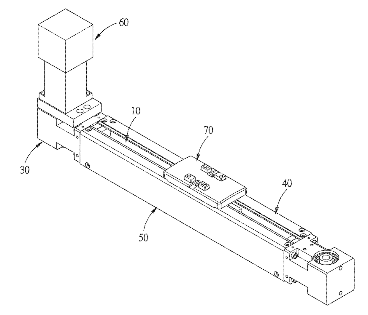
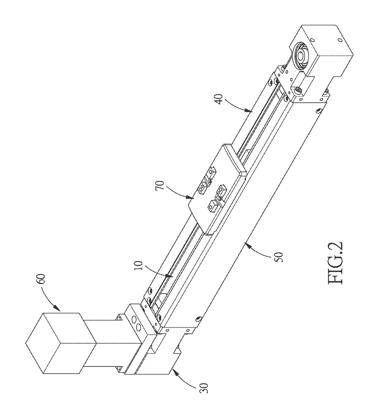
[0033]Referring to FIGS. 2-5, a belt driven linear actuator in accordance with a preferred embodiment of the present invention comprises: a base 10, a linearly movable unit 20, a belt driven unit 30, a first cover 40, a second cover 50, a drive source 60, and a slide block 70.

[0034]A direction connected between two ends of the base 10 is defined as a length direction L. The base 10 is an L-shaped structure with a first assembling portion 11 and a second assembling portion 12 which are connected to each other. Each of the first assembling portion 11 and the second assembling portion 12 is a sheet structure. The first assembling portion 11 extends at least in the length direction L and a width direction W. The second assembling portion 12 extends a...


PUM


Abstract

A belt driven linear actuator includes: a base, a linearly movable unit, a belt driven unit, a first cover, a second cover, a drive source, and a slide block. With the first and second covers removably disposed on the base, the first and second covers can be located at different positions to define different gaps in different directions, so as to allow the slide block to be assembled in different directions, and reduce the restriction on the assembling direction of the drive source. Besides, the width of the base is equal to the height of the base, and the height of the cover portion is equal to the height and the width of the base, which allows the base to be assembled in the same position while in different directions.

Description

BACKGROUNDField of the Invention[0001]The present invention relates to a linear actuator, and more particularly to a belt driven linear actuator.Related Prior Art[0002]Linear guideways have been widely used as a medium for linear motion transmission due to the advantages of high precision, good load capacity, high speed transmission, and being easy to assemble.[0003]The linear guideways generally include ball screw driven linear guideway and belt driven linear guideway. As shown in FIG. 1, a belt driven linear guideway A comprises: a base A1, a rail A2, a slide block A3 slidably mounted on the rail A2, and a belt A4 disposed on the slide block A3. The cycling motion of the belt A4 causes repeated back and forth displacement of the slide block A3 along the rail A2.[0004]The base A1 is a U-shaped structure with a gap A11. A cover A5 covers the gap A11 and fixed to the belt A4, so that the cover A5 moves along with the slide block A3, and some components that need to be driven by the b...

Claims


Application Information

Patent Timeline
Patent Type & Authority Applications(United States)
IPC IPC(8): B65G25/06
CPCB65G2207/30B65G25/06F16H19/0622F16H2019/0686
Inventor PENG, TSUNG-WEN
Owner HIWIN TECH
Why Eureka
Try Eureka