Transmission for pump such as hydraulic fracturing pump

a technology of hydraulic fracturing pump and pump body, which is applied in the direction of piston pump, gearing, borehole/well accessories, etc., can solve the problems of reducing the efficiency of the pump assembly, affecting the operation of operators dealing with continuous duty operations, and affecting the performance of the fluid end

Inactive Publication Date: 2017-08-17
S P M FLOW CONTROL
View PDF3 Cites 131 Cited by
  • Summary
  • Abstract
  • Description
  • Claims
  • Application Information

AI Technical Summary

Problems solved by technology

In some cases, the configuration of the transmission(s) and / or the gear reducer(s) may decrease the efficiency of the pump assembly, thereby constraining the performance of the fluid end.
Such constrained performance presents a problem for operators dealing with continuous duty operations, harsh downhole environments, and multiple extended-reach lateral wells.
Further, the configuration of the transmission(s) and / or the gear reducer(s) may adversely affect the size and weight of the pump assembly, and thus the transportability and overall footprint of the pump assembly at the wellsite.
Finally, the separate and distinct nature of the motor, the pump, the transmission(s), and the gear reducer(s) can make it difficult to inspect, service, or repair the pump assembly, and / or to coordinate the inspection, service, repair, or replacement of the motor, the pump, the transmission(s), and / or the gear reducer(s).

Method used


Image

  • Transmission for pump such as hydraulic fracturing pump
  • Transmission for pump such as hydraulic fracturing pump
  • Transmission for pump such as hydraulic fracturing pump

Examples


Embodiment Construction

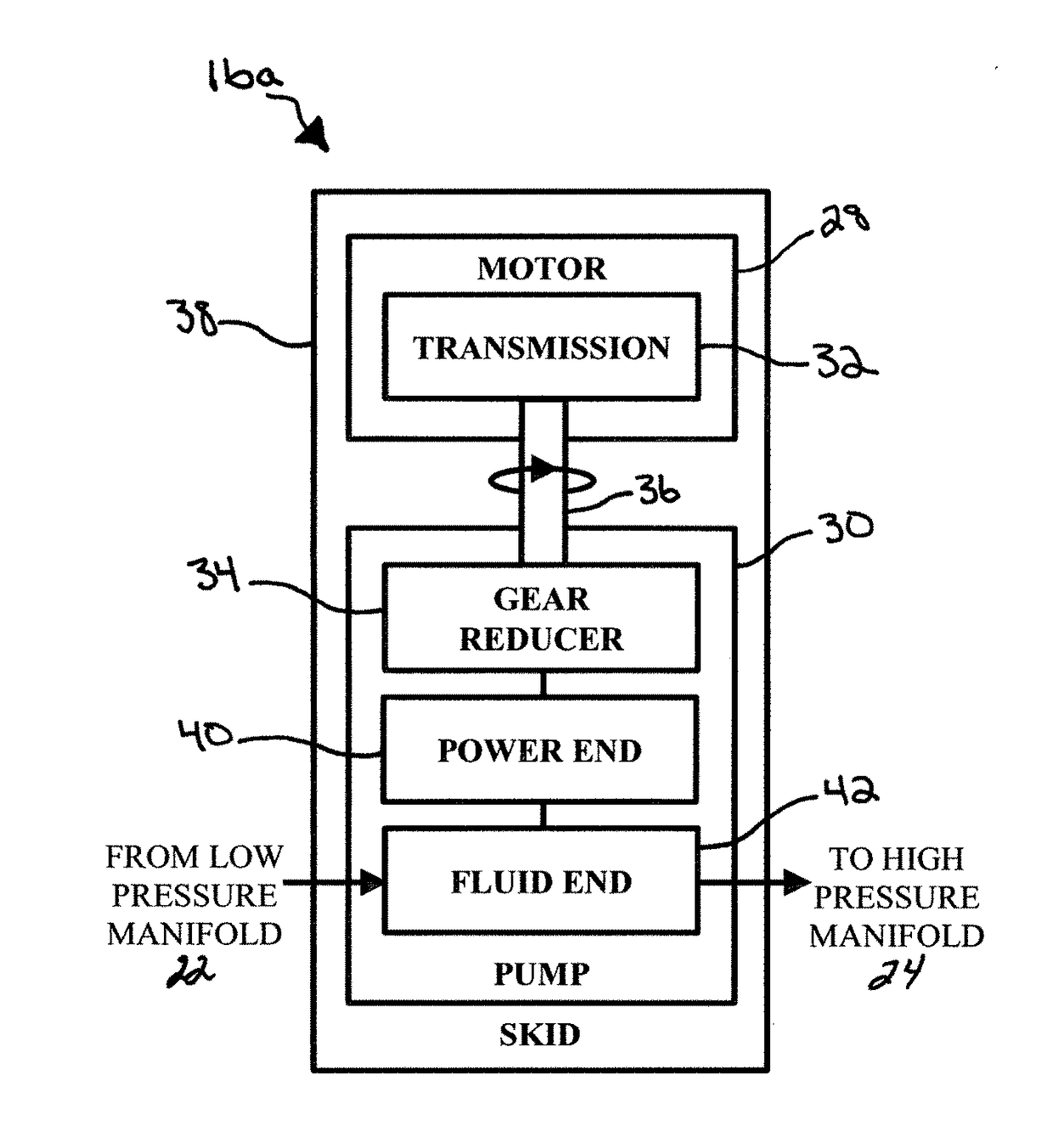
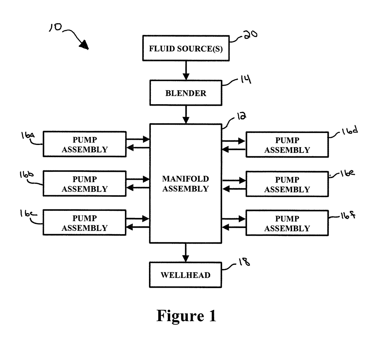
[0033]In an example embodiment, as illustrated in FIG. 1, a system is generally referred to by the reference numeral 10 and includes a manifold assembly 12. The manifold assembly 12 is in fluid communication with a blender 14, pump assemblies 16a-f, and a wellhead 18. One or more fluid sources 20 are in fluid communication with the blender 14. The wellhead 18 is located at the top or head of an oil and gas wellbore (not shown), which penetrates one or more subterranean formations (not shown), and is used in oil and gas exploration and production operations. In several example embodiments, the wellhead 18 is in fluid communication with the manifold assembly 12. In an example embodiment, the one or more fluid sources 20 include one or more fluid storage tanks, other types of fluid sources, natural water features, or any combination thereof.

[0034]In an example embodiment, the system 10 is part of a hydraulic fracturing (or “frac”) system, which may be used to facilitate oil and gas exp...


PUM


Abstract

An apparatus and method according to which a fluid, such as a fracturing fluid, is pressurized. The apparatus includes a motor that produces a first rotational output including a first angular velocity, a pump operably coupled to the motor, the pump comprising a fluid end and a power end operably coupled to the fluid end, and a transmission operably coupled between the motor and the pump. The transmission receives the first rotational output as a first rotational input, the first rotational input including the first angular velocity, and converts the first rotational input into a second rotational output, the second rotational output including a second angular velocity. The power end receives the second rotational output as a second rotational input, the second rotational input including the second angular velocity. In some embodiments, the transmission is directly connected to, or part of, the pump and the motor.

Description

CROSS-REFERENCE TO RELATED APPLICATION[0001]This application claims the benefit of the filing date of, and priority to, U.S. Application No. 62 / 294,013, filed Feb. 11, 2016, the entire disclosure of which is hereby incorporated herein by reference.TECHNICAL FIELD[0002]This disclosure relates in general to pumps and, in particular, a transmission for a pump such as a hydraulic fracturing pump or any reciprocating pump assembly that may be used in one or more other applications or environments.BACKGROUND OF THE DISCLOSURE[0003]A pump assembly may include a motor, a pump, one or more transmissions, and one or more gear reducers, with the motor, the pump, the transmission(s), and the gear reducer(s) being separate and distinct from one another. Such a pump assembly may be used to hydraulically fracture (or “frac”) a subterranean formation by pressurizing a fluid for conveyance to a wellbore that extends within a subterranean formation, thereby facilitating oil and gas exploration and pr...

Claims


Application Information

Patent Timeline
Patent Type & Authority Applications(United States)
IPC IPC(8): F04B9/02F04B19/20E21B43/26
CPCF04B9/02E21B43/26F16H2200/0047F16H3/02F16H19/02F04B19/20F04B47/00F04B53/22E21B43/2607
Inventor BUCKLEY, CHRISTOPHER
Owner S P M FLOW CONTROL
Why Eureka
Try Eureka