Eureka AIR delivers breakthrough ideas for toughest innovation challenges, trusted by R&D personnel around the world.

Image pickup apparatus

Inactive Publication Date: 2017-08-17
CANON KK
View PDF3 Cites 0 Cited by
  • Summary
  • Abstract
  • Description
  • Claims
  • Application Information

AI Technical Summary

Benefits of technology

The invention is an image pickup apparatus that reduces the movement of a small mirror using a simple and affordable design. The apparatus includes a motor, a main mirror holder, a sub mirror holder, and a driving pin. The main mirror holder rotates between a position where it is within the image pickup optical path (mirror down) and a position where it is outside the optical path (mirror up). The sub mirror holder is supported by the main mirror holder and rotates with it. The driving pin rotates in response to the driving of the motor and causes the main mirror holder and the sub mirror holder to rotate. The driving pin has an abutting part that comes into contact with the motor when it drives. This abutting part helps prevent the sub mirror holder from being bound when the main mirror holder reaches its maximum elevation.

Problems solved by technology

However, the conventional art disclosed in Japanese Patent Laid-Open No. 2014-219582 requires the buffer member and a space to arrange the buffer member.

Method used


Image

  • Image pickup apparatus
  • Image pickup apparatus
  • Image pickup apparatus

Examples


first example

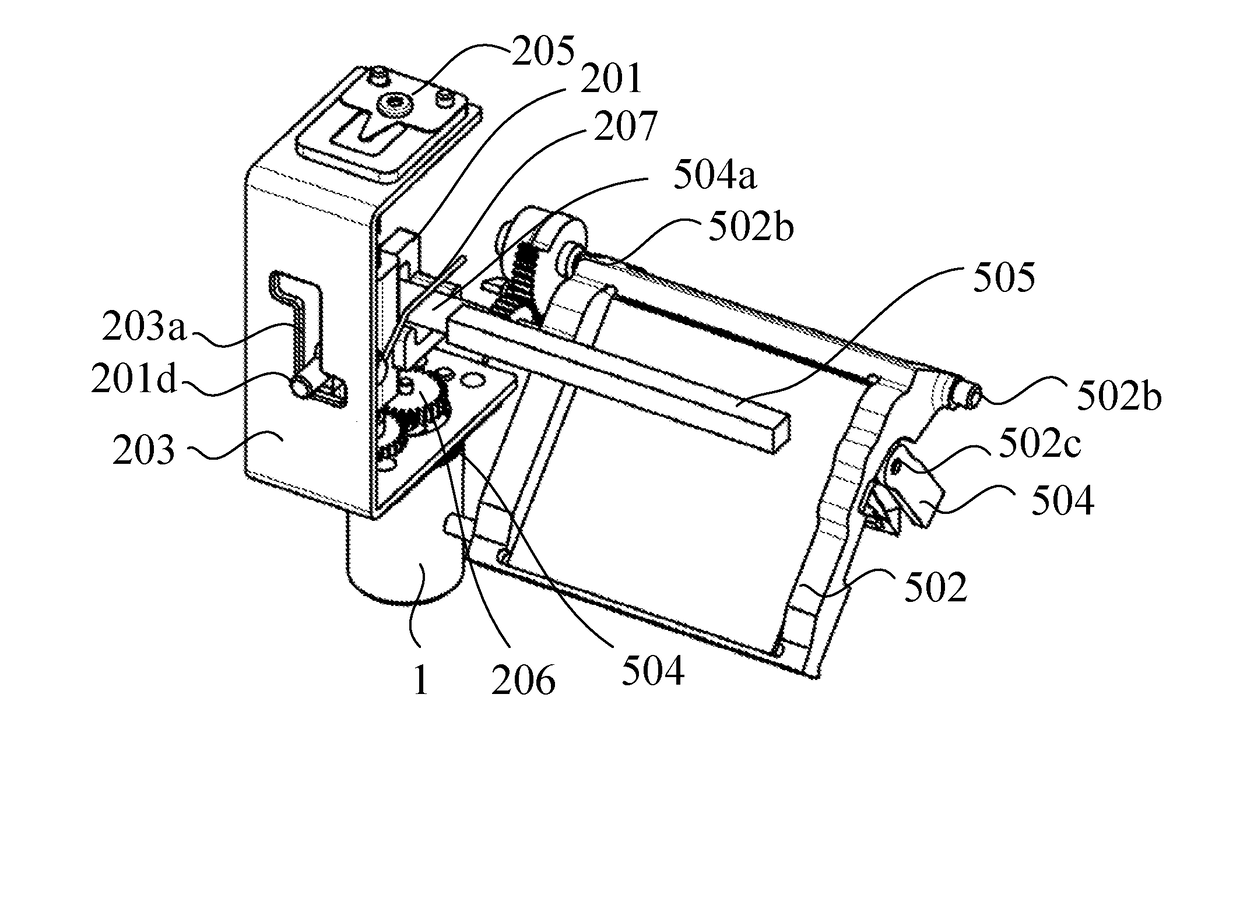
[0055]With reference to FIGS. 7A to 7D, the mirror drive mechanism 112 will be explained. FIGS. 7A to 7D are explanatory views of the mirror drive mechanism 112. The mirror drive mechanism 112 includes a mirror drive holder (mirror driving unit) 201, a lead screw 202 and a drive unit base 203.

[0056]The mirror drive holder 201 holds the main mirror holder 502. The main mirror holder 502 is provided with an axis part 502c that rotatably supports the sub mirror holder 504. The sub mirror holder 504 is provided with a driving pin 504a that is arranged coaxially with the axis part 502c. The mirror holder 201 includes a drive nut part 201a engaged with the lead screw 202, a spring mount part 201b where a winding part of a torsion spring 207 is freely fitted, a driving pin engaging part 201c where the driving pin 504a is inserted, and a protruding part 201d.

[0057]The lead screw 202, a motor base 204 holding the motor 1, and a plate spring 205 urging the lead screw 202 to the motor 1 are a...

second example

[0076]With reference to FIGS. 11A to 11C, an adjustment method of drive control (mirror drive control) of the mirror unit 500 will be explained. FIGS. 11A to 11C are explanatory diagrams of the mirror drive.

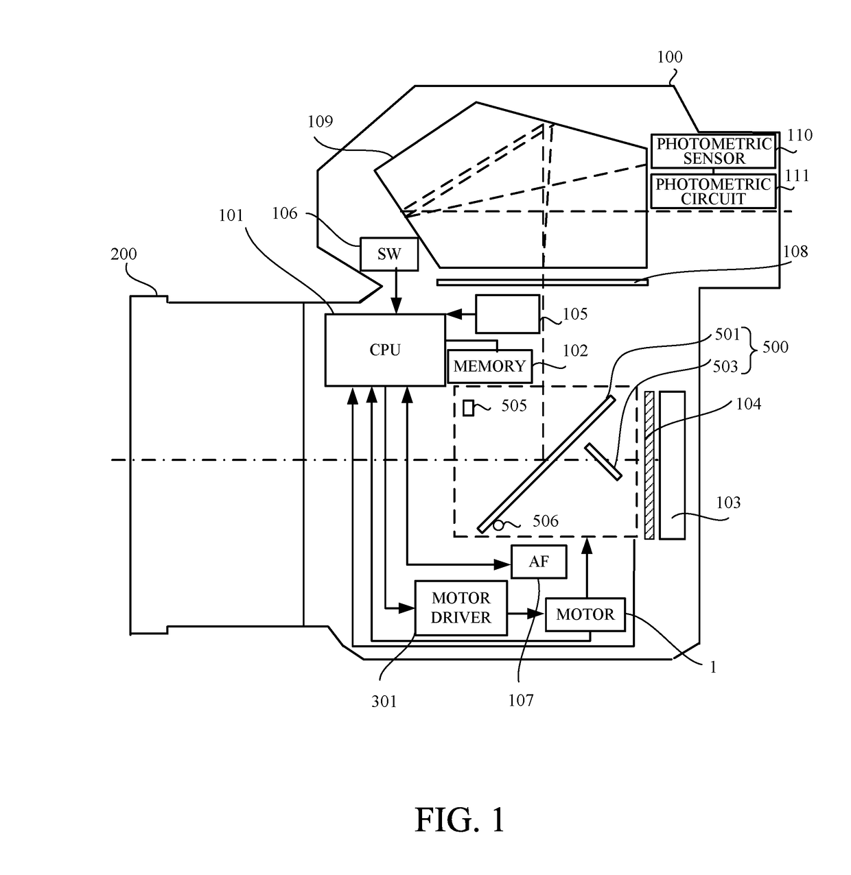
[0077]FIG. 11A illustrates a mirror down state (hereinafter referred to as “first state”) where the main mirror holder 502 and the sub mirror holder 504 are arranged in an image pickup optical path, that is, are arranged at a mirror down position. When the mirror unit 500 is in the first state, the photographing light flux transmitted through the lens 200 is separated by the main mirror 501. The photographing light flux reflected by the main mirror 501 is imaged on a focusing plate 108. A pentaprism 109 guides an object image imaged on the focusing plate 108 to a photometric sensor 110. The photometric sensor 110 detects a part of the object image using a light receiving element divided to correspond to each area on a viewing screen. A photometric circuit 111 converts an output s...

third example

[0094]As mirror drive of this example is the same as that of the second example, detailed explanations are omitted. FIG. 14 is an exploded perspective view of the mirror unit 500 and the mirror box 1000 according to this example. The main mirror holder 502 is attached to the mirror box 1000 by an axis pressure plate 1506 to rotate around a rotational axis 1502a. The main holder 502 is provided with an abutting surface 1502b that abuts against the mirror down stopper 506 when the mirror unit 500 is in the first state. In this example, the mirror down stopper 506 is formed by an eccentric pin, and thus rotating the mirror down stopper 506 can adjust the mirror down position of the main mirror holder 502. Moreover, the main mirror holder 502 is provided with a sub mirror rotational axis part 1502d engaging with a rotation center hole 1504a of the sub mirror holder 504.

[0095]The sub mirror holder 504 is supported by the main mirror holder 502 to rotate around the sub mirror rotational a...


PUM


Abstract

An image pickup apparatus includes a main mirror holder rotating between a mirror down position in an image pickup optical path and a mirror up position outside the image pickup optical path in accordance with drive of a mirror driving unit, which drives in accordance with rotation of a motor, a sub mirror holder being supported by the main mirror holder to abut against the main mirror holder positioned at the mirror up position, and a driving pin rotating in accordance with the drive of the mirror driving unit and rotating the main and sub mirror holders. The driving pin includes an abutting part that abuts against the mirror driving unit while the mirror driving unit drives. The abutting part is provided with a reduction structure to reduce a bound of the sub mirror holder when the main mirror holder reaches the mirror up position.

Description

BACKGROUND OF THE INVENTION[0001]Field of the Invention[0002]The present invention relates to an image pickup apparatus.[0003]Description of the Related Art[0004]A single-lens reflex camera conventionally includes a quick return mirror mechanism using a direct drive method to drive a main mirror directly. Japanese Patent Laid-Open No. 2014-219582 discloses a mirror driving apparatus where a buffer member is arranged on a side surface part of a sun gear to reduce a bound generated by rotation of a main mirror and a sub mirror.[0005]However, the conventional art disclosed in Japanese Patent Laid-Open No. 2014-219582 requires the buffer member and a space to arrange the buffer member.SUMMARY OF THE INVENTION[0006]In view of the problem, an object of the present invention is to provide an image pickup apparatus capable of reducing a bound of a sub mirror using a simple and inexpensive configuration.[0007]An image pickup apparatus according to one aspect of the present invention includes...

Claims


Application Information

Patent Timeline
IPC IPC(8): G03B19/12
CPCG03B2217/002G03B19/12G03B17/17
Inventor KOJIMA, NOBUHISA
Owner CANON KK
Why Eureka
Eureka Blog
Learn More