Program generation device generating program for groove machining by drilling

a technology of program generation device and groove machining, which is applied in the direction of programme control, total factory control, instruments, etc., can solve the problems of requiring a great deal of machining time, unable to achieve high feed rate, and requiring a large amount of machining time, so as to achieve stable machining, reduce vibration and abnormal load, and generate easily

Active Publication Date: 2017-08-17
FANUC LTD
View PDF1 Cites 3 Cited by
  • Summary
  • Abstract
  • Description
  • Claims
  • Application Information

AI Technical Summary

Benefits of technology

[0017]According to the present invention, a program for groove machining by drilling, in which a cusp height and machining time are taken into account, can be easily generated and further, a machining order in

Problems solved by technology

In the case of a material hard to cut, machining in a direction orthogonal to a tool (spindle) axis direction is mechanically hard to be performed and machining chatter easily occurs, so that machining cannot be performed at a high feed rate, thereby requiring a great deal of machining time.
This calculation and balancing have been an operation which takes much time and labor of an operator.
Therefore, as a drilling tool tends to violently

Method used


Image

  • Program generation device generating program for groove machining by drilling
  • Program generation device generating program for groove machining by drilling
  • Program generation device generating program for groove machining by drilling

Examples


Embodiment Construction

[0029]An embodiment of the present invention will be described below with reference to the accompanying drawings. A basic principle of the present invention will be first described.

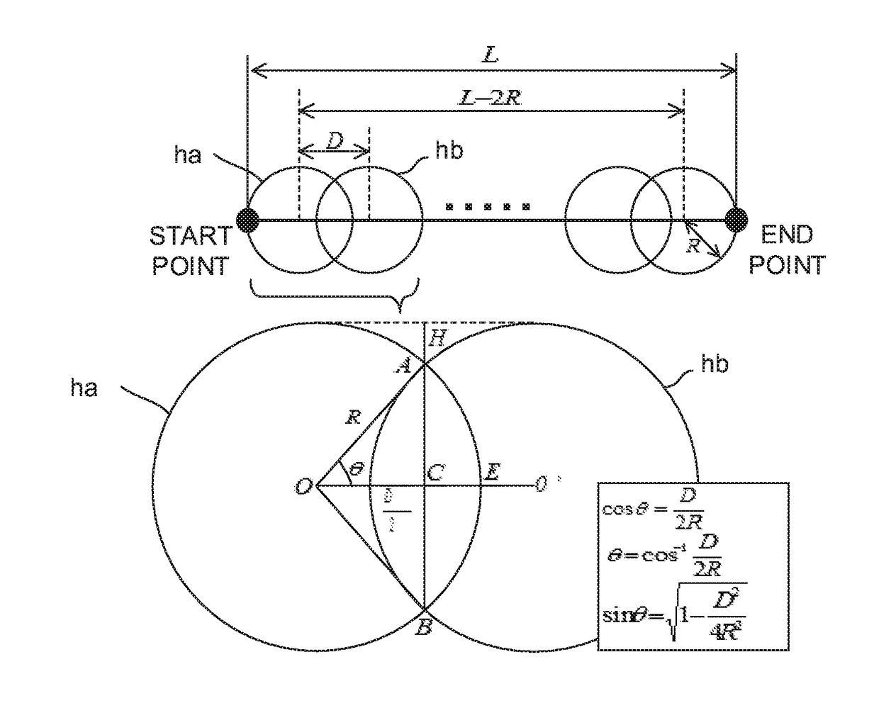
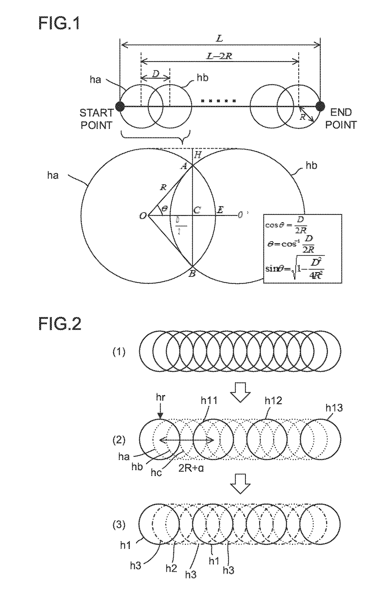
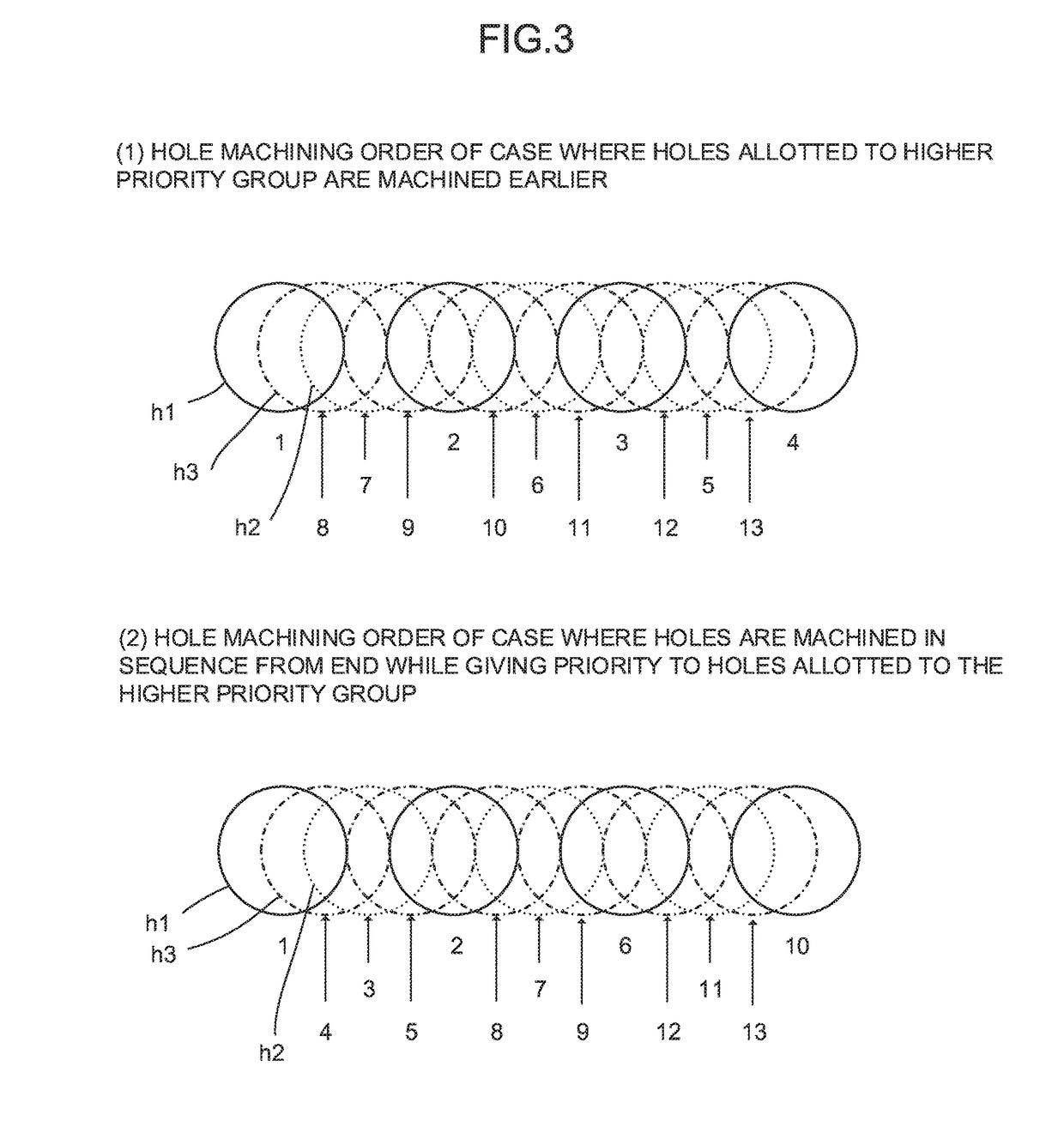
[0030]A program generation device according to the present invention receives specifications of a cusp height and the like specified by an operator so as to calculate drilling positions and machining time based on the specified values and obtain a hole machining order in which bias in removal stocks are taken into account. Examples of values specified by an operator include a tool radius, a cusp height, a groove shape, and a feed rate. The program generation device according to the present invention obtains the number of holes, an inter-hole distance (hole positions), a percentage of an area in which holes adjacent to each other are overlapped with each other, and a hole machining order based on these specified values in groove machining by continuous drilling.

[0031]The program generation device according...


PUM


Abstract

A program generation device generates a program for controlling machining of a groove which is performed by machining a plurality of holes on a workpiece. The program generation device receives specified values including a tool radius, a groove shape (a length of the groove), and a cusp height and calculates positions of the plurality of holes based on the specified values which are received. Then, the program generation device calculates a machining order of the plurality of holes based on the specified values and respective values calculated by a hole machining set value calculation unit so that a bias is not generated in a removal stock for a tool in machining.

Description

BACKGROUND OF THE INVENTION[0001]1. Field of the Invention[0002]The present invention relates to a program generation device which generates a program for groove machining by drilling.[0003]2. Description of the Related Art[0004]Machining of a groove shape is generally performed by machining methods as those illustrated in FIGS. 9A to 9C. “Ramping” illustrated in FIG. 9A is a machining method for forming a groove by cutting a workpiece by a tool which is rotating and is tilted with respect to the workpiece. Further, “extension from hole forming to a groove shape” illustrated in FIG. 9B is a machining method in which after holes are formed on a workpiece by helical machining or drilling, a groove is formed from the holes by lateral surface milling or the like. Meanwhile, “continuous drilling” illustrated in FIG. 9C is a machining method in which a boring such as drilling is repeatedly performed along a groove shape and this “continuous drilling” is mainly used for groove machining (r...

Claims


Application Information

Patent Timeline
IPC IPC(8): G05B19/042G05B19/402
CPCG05B19/0426G05B2219/50036G05B2219/45129G05B19/402G05B19/4097G05B2219/45148G05B2219/49119Y02P90/02
Inventor KAYANUMA, TOMOKAZU
Owner FANUC LTD
Why Eureka
Try Eureka