Wheel disc arrangement

a technology of discs and wheels, applied in the direction of engine fuction, leakage prevention, machine/engine, etc., can solve the problems of affecting the strength of the wheel disk or of the blade device, damaging the wheel disk or the blade device, etc., to achieve simple and cost-effective production, simple manual release of the latching connection, and reliable latching connection

Inactive Publication Date: 2017-08-24
SIEMENS AG
View PDF6 Cites 3 Cited by
  • Summary
  • Abstract
  • Description
  • Claims
  • Application Information

AI Technical Summary

Benefits of technology

[0009]Advantageously, the at least one latching depression is annular, thus achieving a construction that is simple and cost-effective to produce.
[0010]According to one embodiment of the present invention, there are provided two radially mutually opposite latching projections, thus achieving a very reliable latching connection.
[0011]Advantageously, at least one actuation element, which can be actuated manually or using a tool, is provided on the bolt for the purpose of releasing the latching connection. This ensures simple manual release of the latching connection.

Problems solved by technology

However, one problem of a securing device so formed is that the notch effect associated with the tapped hole provided in the wheel disk or in the blade device negatively affects the strength of the wheel disk or of the blade device, and can give rise to corresponding problems.
Furthermore, it is often the case that screws cannot be removed during servicing, which implies laborious drilling-out of the screw connection, thereby damaging the wheel disk or the blade device and thus a costly component.

Method used


Image

  • Wheel disc arrangement
  • Wheel disc arrangement
  • Wheel disc arrangement

Examples


first embodiment

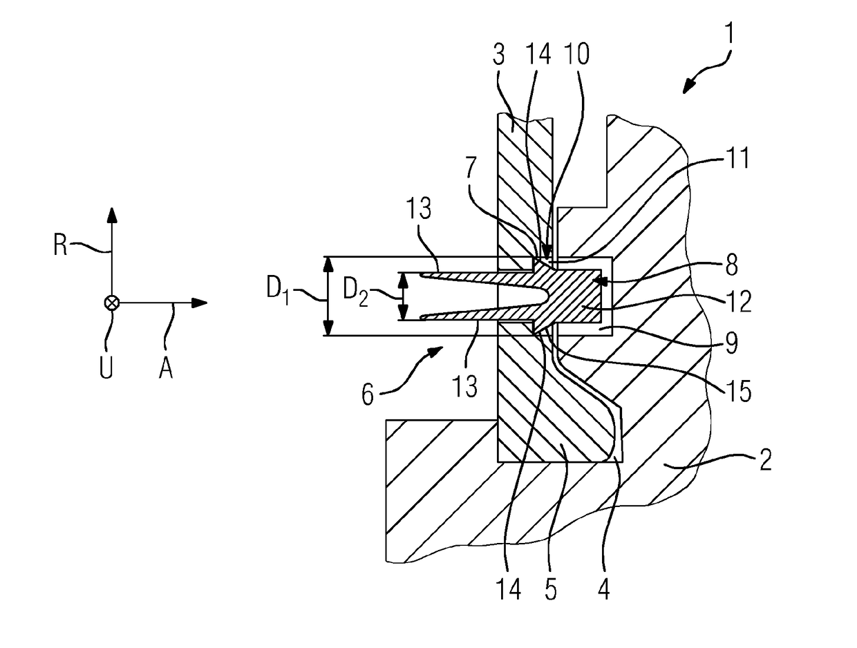
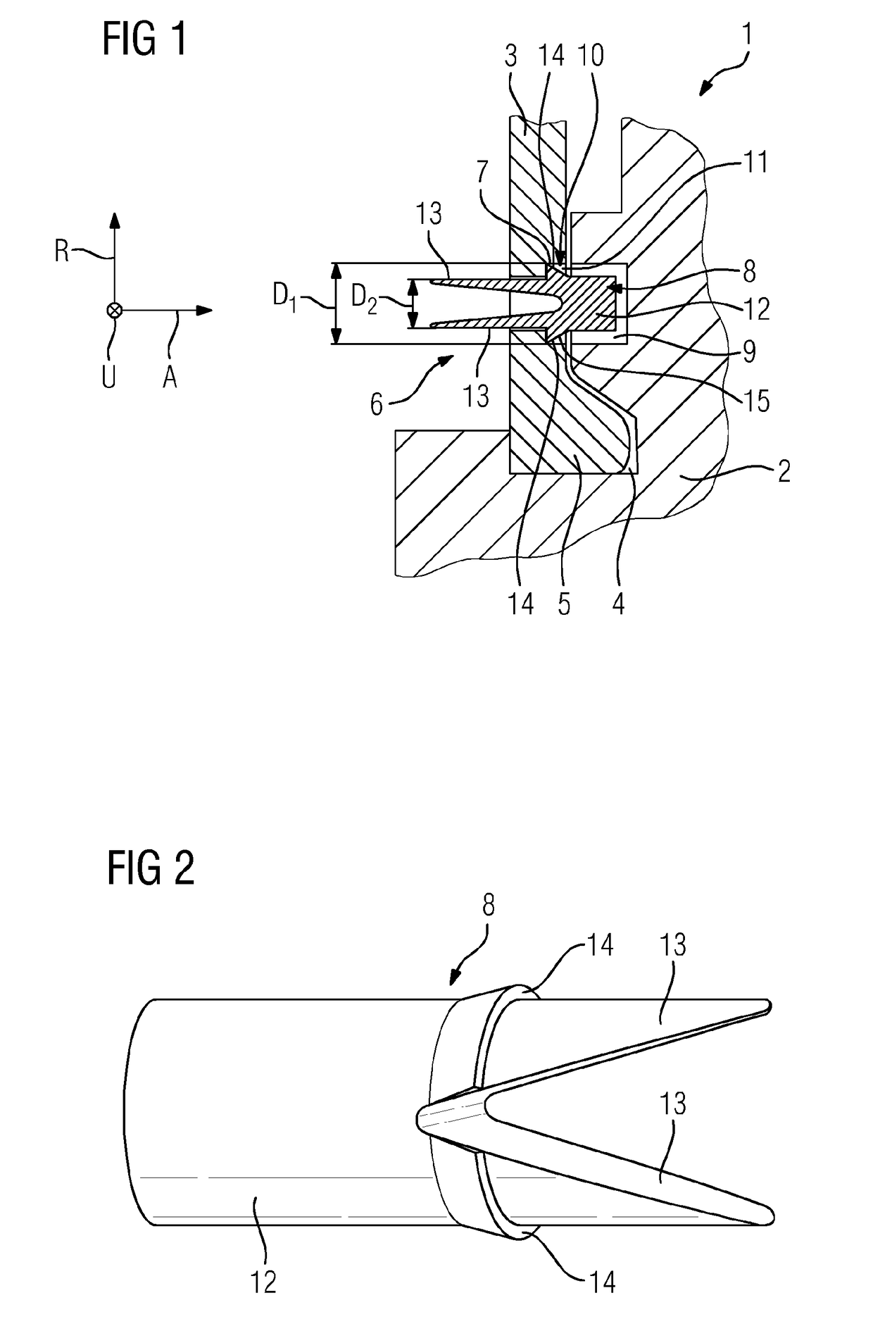
[0023]FIGS. 1 to 3 show a detail of a wheel disk arrangement 1 according to the present invention. The wheel disk arrangement 1 comprises a wheel disk 2, multiple blade devices (not shown in greater detail) which are attached along an outer circumference of the wheel disk 2, and multiple sealing plates 3 which extend between the wheel disk 2 and the blade devices, and are received such that they can be displaced in the circumferential direction U. More precisely, the sealing plates 3 are inserted into annular grooves which are arranged spaced apart from one another in the radial direction R, the annular grooves being formed on one hand in the wheel disk 2 and on the other hand in the blade devices. FIG. 1 shows only the undercut annular groove 4 which is formed in the wheel disk 2 and into which are inserted beads 5 formed on the radially inward oriented edges of the sealing plates 3.

[0024]In order to secure the sealing plates 3 against displacement in the circumferential direction ...

second embodiment

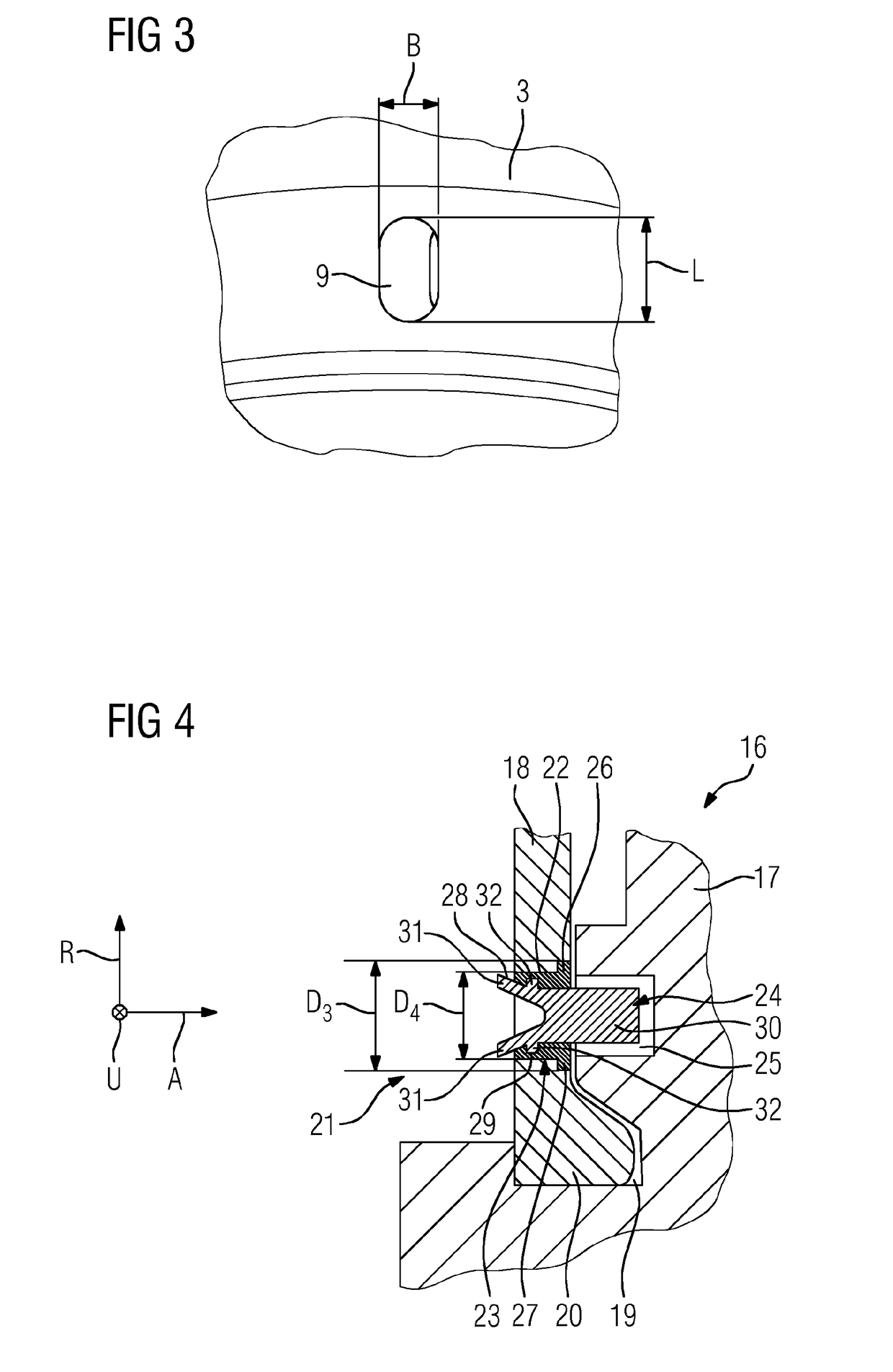
[0029]FIGS. 4 to 6 show a wheel disk arrangement 16 according to the present invention. The wheel disk arrangement 16 comprises a wheel disk 17, multiple blade devices (not shown in greater detail) which are attached along an outer circumference of the wheel disk 17, and multiple sealing plates 18 which extend between the wheel disk 17 and the blade devices, and are received such that they can be displaced in the circumferential direction U. More precisely, the sealing plates 18 are inserted into annular grooves which are arranged spaced apart from one another in the radial direction R, the annular grooves being formed on one hand in the wheel disk 17 and on the other hand in the blade devices. FIG. 4 shows only the undercut annular groove 19 which is formed in the wheel disk 17 and into which are inserted beads 20 formed on the radially inward oriented edges of the sealing plates 18.

[0030]In order to secure the sealing plates 18 against displacement in the circumferential direction...


PUM


Abstract

A wheel disc arrangement having a wheel disc, having multiple vane devices which are fastened along an outer circumference of the wheel disc, having at least one sealing plate received between the wheel disc and the vane devices so as to be displaceable in a circumferential direction, and having at least one securing device designed so as to secure the sealing plate against a displacement in the circumferential direction, wherein the securing device has a bolt, which extends through a passage opening provided in the sealing plate, and a recess, which is provided on the wheel disc or on a vane device, which recess receives the free end of the bolt and the wall of which recess limits a movement of the bolt in the circumferential direction, wherein the bolt is, in an axial direction, secured on the sealing plate against undesired release by way of a detent connection.

Description

CROSS REFERENCE TO RELATED APPLICATIONS[0001]This application is the U.S. National Stage of International Application No. PCT / EP2015 / 073261 filed Oct. 8, 2015, and claims the benefit thereof. The International Application claims the benefit of European Application No. EP14191068 filed Oct. 30, 2014. All of the applications are incorporated by reference herein in their entirety.FIELD OF INVENTION[0002]The present invention relates to a wheel disk arrangement having a wheel disk, multiple blade devices which are attached along an outer circumference of the wheel disk, at least one sealing plate which is received between the wheel disk and the blade devices such that it can be displaced in the circumferential direction, and at least one securing device designed so as to secure the sealing plate against displacement in the circumferential direction.BACKGROUND OF INVENTION[0003]Wheel disk arrangements of the type stated at the outset are known in the prior art. They form components of ro...

Claims


Application Information

Patent Timeline
Patent Type & Authority Applications(United States)
IPC IPC(8): F01D11/00F01D5/32F01D5/02
CPCF01D11/006F01D5/02F05D2260/30F05D2220/32F01D5/32F01D5/3015F05D2230/64F05D2260/36
Inventor HOELL, HARALDKAMPKA, KEVINKOLK, KARSTENLANGE, MARCSCHRODER, PETERVEITSMAN, VYACHESLAV
Owner SIEMENS AG
Why Eureka
Try Eureka