
Hydrodynamic torque converter having a turbine shell with stiffeners

Inactive Publication Date: 2001-07-17
MANNESMANN SACHS AG
View PDF5 Cites 4 Cited by
  • Summary
  • Abstract
  • Description
  • Claims
  • Application Information

AI Technical Summary

Benefits of technology

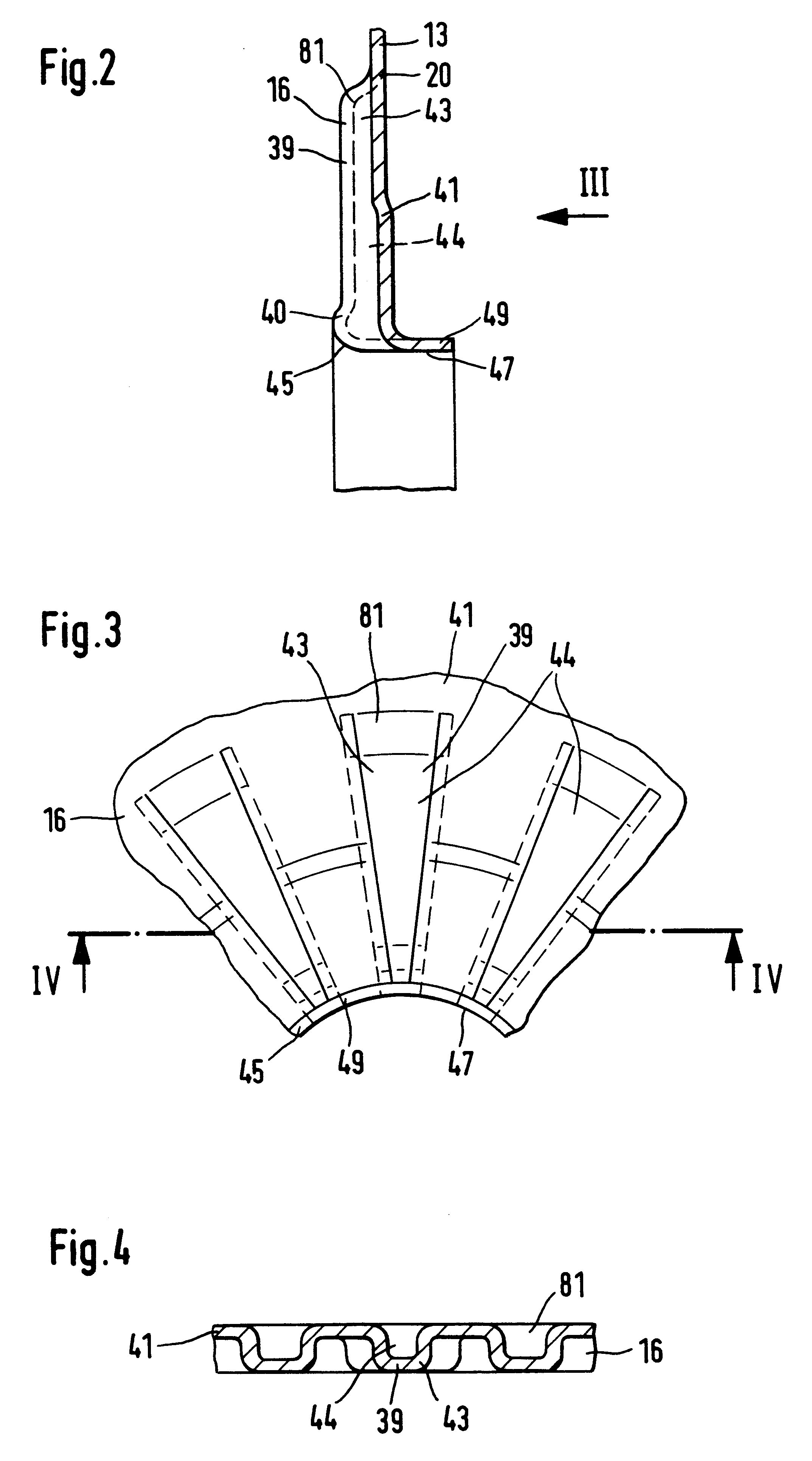
The radially inner end of the turbine shell has a bearing surface for mounting in position on the turbine hub. For the benefit of low surface pressure, this bearing surface, despite a small wall thickness of the turbine shell, may be designed to be relatively large if this bearing surface is created by bending the radially inner end of the turbine shell. A further advantage of such a bending is the firm connection of the turbine shell to the turbine hub via a butt weld. This may be effected with a laser welding unit and, compared with other welding processes, which require increased preparatory measures, is cost-effective and simple to produce.

Problems solved by technology

The above-described prior art torque converter is comparatively complicated to produce and is comparatively expensive because, on the one hand, it has a turbine hub which is complicated with regard to its shape with the radial flange and also has to be connected to the turbine shell via labor-intensive riveting and, on the other hand, the supporting ring between the freewheel and the adjacent axial abutment requires grooving for the throughflow of converter fluid.
This grooving also results in a reduced contact surface of the supporting ring on the adjacent component causing an increased surface pressure on the supporting ring.

Method used


Image

  • Hydrodynamic torque converter having a turbine shell with stiffeners
  • Hydrodynamic torque converter having a turbine shell with stiffeners
  • Hydrodynamic torque converter having a turbine shell with stiffeners

Examples


Embodiment Construction

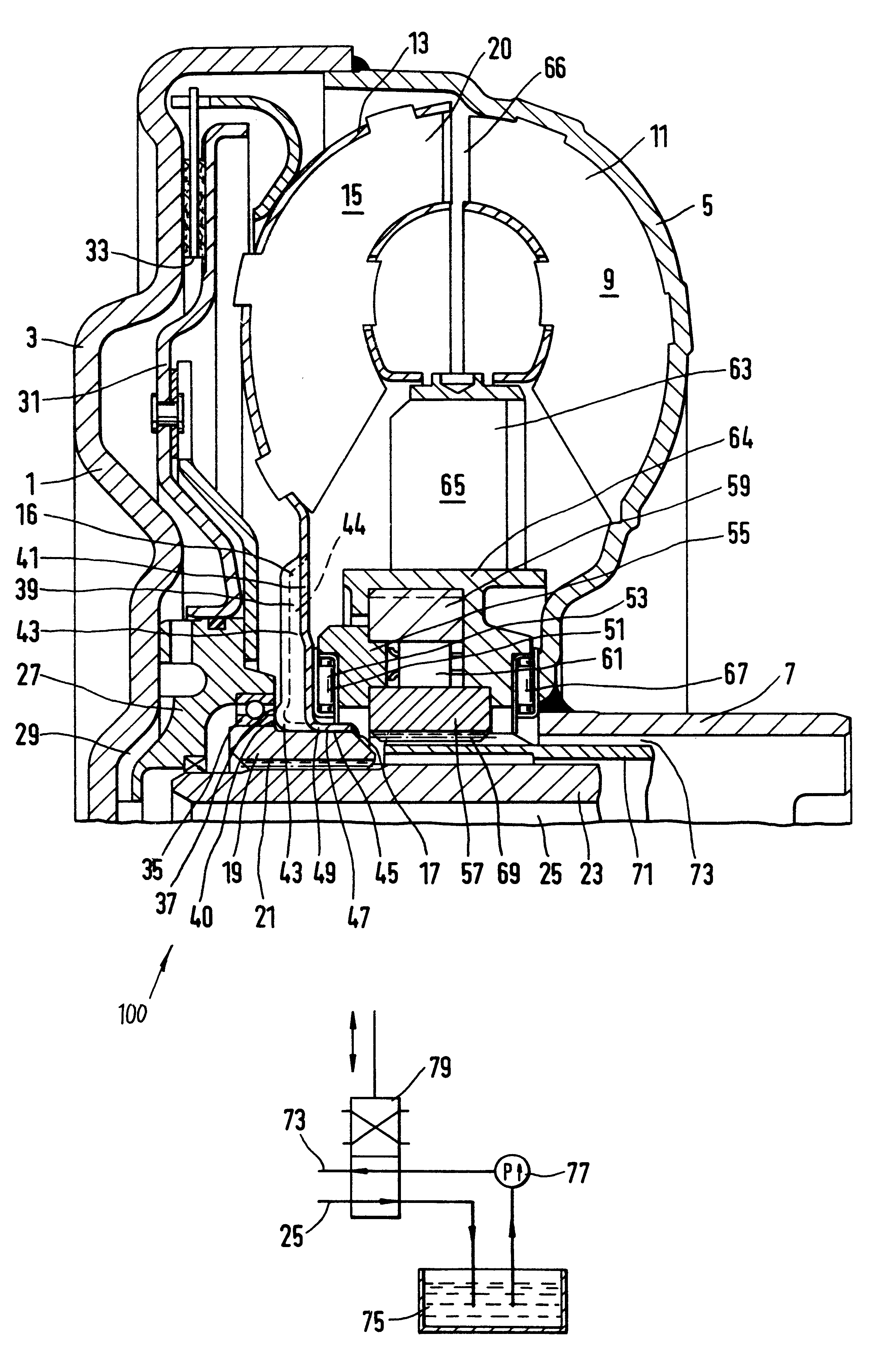
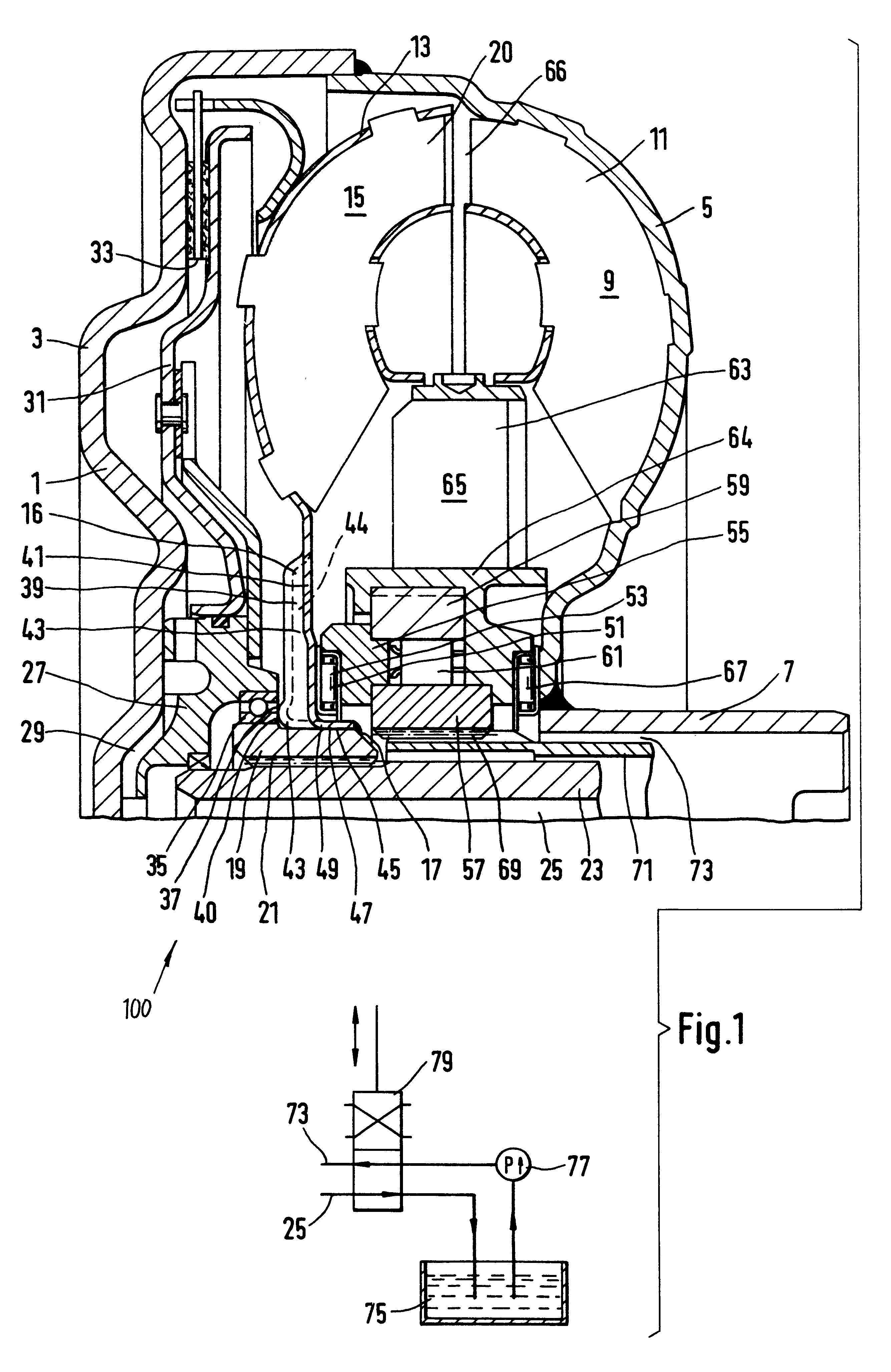
A hydrodynamic torque converter 100 with a hydrodynamic circuit 66 according to an embodiment of the present invention is shown in FIG. 1 having a converter housing 1 with a radial flange 3 on a drive side of the torque converter. Fastened to an outer circumferential region of the radial flange 3 is an impeller shell 5 which includes an impeller hub 7 on its radially inner end. The impeller shell 5 has blading 9 for forming a pump impeller 11. The pump impeller 11 interacts with a turbine wheel 20 comprising a turbine shell 13 with blading 15. A radially inner end of the turbine shell 13 includes a blade root 16, which will be described in more detail later. The blade root 16 is connected via a butt weld 17 to a turbine hub 19, which is of essentially annular design and, radially on the inside, is in rotary connection with an output shaft 23 via a tooth system 21. The output shaft 23, which may be formed, for example, by a transmission input shaft has a center bore 25 at its end fac...


PUM


Abstract

A hydrodynamic torque converter a hydrodynamic circuit has at least a pump impeller and a turbine wheel. The turbine wheel has a turbine shell with a blading and a turbine hub which is in rotary connection with an output shaft. The turbine shell extends radially inward between an extension region of axial abutments and is provided with stiffeners.

Description

1. Field of the InventionThe invention relates to a hydrodynamic torque converter having a hydrodynamic circuit including a pump wheel and a turbine wheel, wherein a turbine shell of the turbine wheel extends between two axial abutments for axially positioning the turbine wheel.2. Description of the Related ArtA prior art hydrodynamic torque converter having a hydrodynamic circuit is disclosed in DE 44 23 640 A1 (see FIG. 1) which has a pump impeller, a turbine wheel and a stator. The turbine wheel has a turbine shell, which is formed with blading. A radially inner region of the turbine shell is connected in a rotationally locked manner to a radial flange of a turbine hub via riveting. The radial flange of the turbine hub interacts with axial abutments, which are provided on both sides and position the turbine wheel axially between a housing hub of the converter housing and the stator. Of course, this radial flange of the turbine hub must have sufficient flexural rigidity to fulfill...

Claims


Application Information

Patent Timeline
IPC IPC(8): F16H45/02F16H45/00
CPCF16H45/02F16H2045/0278F16H2041/246
Inventor SCHODER, BERND
Owner MANNESMANN SACHS AG
Learn More