Method and device for boring holes in soil or rock

a technology of soil or rock and borehole, which is applied in the direction of drilling machines and methods, cutting machines, constructions, etc., can solve the problems of low strength of jacket tubes, inability to accurately drill, and low friction resistance of jacket tubes, so as to achieve accurate bores, large friction resistance, and high friction resistance

Inactive Publication Date: 2006-08-10
ALWAG TUNNELAUSBAU GMBH
View PDF7 Cites 4 Cited by
  • Summary
  • Abstract
  • Description
  • Claims
  • Application Information

AI Technical Summary

Benefits of technology

[0016] As already indicated above several times, the envelope tube ensures targeted and accurate drilling, which is further supported in that the outer diameter of the envelope tube exceeds the outer diameter of the jacket tube. The outer diameter of the envelope tube can, thus, be precisely tuned to the dimensions of the borehole to be produced, with the envelope tube having an accordingly short length such that the frictional forces generated by the snug abutment of the envelope tube on the inner wall of the borehole can be safely overcome while the adjoining jacket tube having an accordingly reduced diameter can be readily introduced into the interior of the borehole without large friction resistances.
[0017] To assist in the production of an accurate bore, it is proposed according to a further preferred embodiment that the envelope tube has an elevated cross section and / or elevated strength relative to the jacket tube. Due to the fact that the envelope tube has an elevated cross section and / or elevated strength, it will be safeguarded that deviations from the desired drilling direction on account of the strength or rigidity of the envelope tube will be prevented.
[0018] In order to provide a particularly simple and reliable connection of adjoining jacket tube elements, it is proposed according to a further preferred embodiment that, for the connection of adjoining jacket tube elements, sleeve-like elements are provided, each overlapping adjoining end regions of the jacket tube elements and formed, or capable of being formed, with projections or elevations engaging in complementary depressions or recesses provided about the peripheries of the jacket tube elements. Such projections or elevations engaging in complementary depressions or recesses are not only simple and cost-effective to produce, but, unlike conventional screw connections, also enable the reliable connection or coupling of jacket tube sections as a simple connection for extension in the usually rough boring or drilling operation. Moreover, such depressions or recesses and projections or elevations, respectively, will not be as easily damaged as in the case of known screw connections used to extend jacket tube elements.
[0019] For a particularly simple connection of neighboring jacket tube elements, it is proposed according to a further preferred embodiment that the sleeve-like elements are designed to have reduced material cross sections in the region of the projections or elevations, and that the projections or elevations are capable of being formed to correspond with the depressions of the jacket tube elements after the arrangement of the sleeve-like elements on the outer peripheries of the jacket tube elements to be connected.
[0020] In addition to the sleeve-like elements suggested for the connection of neighboring jacket tube elements, it is proposed according to a further preferred embodiment that additional securing elements such as, for instance, pin-shaped studs or spigots are provided for the positioning and / or fixing of the sleeve-like elements so as to enable an accordingly safe maintenance of connection positions.
[0021] For a particularly reliable haulage of excavated material from the region of the drill bit, it is proposed according to a further preferred embodiment that, in the region of fixation of the envelope tube to the drill bit and / or an impact shoe or adapter connected therewith, at least one passage opening for the introduction of excavated material into the annular space formed between the outer periphery of the drill rod assembly and the inner peripheries of the envelope tube and the adjoining jacket tube is provided.

Problems solved by technology

While a merely tensilely stressed and accordingly thin-walled jacket tube, in particular, offers advantages through an accordingly reduced force introduction for the insertion of the jacket tube, such a thin-walled jacket tube frequently involves the drawback of rendering accurate drilling impossible on account of the low strength of the jacket tube.
On the other hand, accordingly sturdily designed envelope tubes involve the disadvantage of exerting a high frictional load on the peripheral walls of the borehole to be produced, with a separate and accordingly sturdy drive mechanism being, as a rule, additionally required for the introduction of the envelope tube.

Method used


Image

  • Method and device for boring holes in soil or rock
  • Method and device for boring holes in soil or rock
  • Method and device for boring holes in soil or rock

Examples


Embodiment Construction

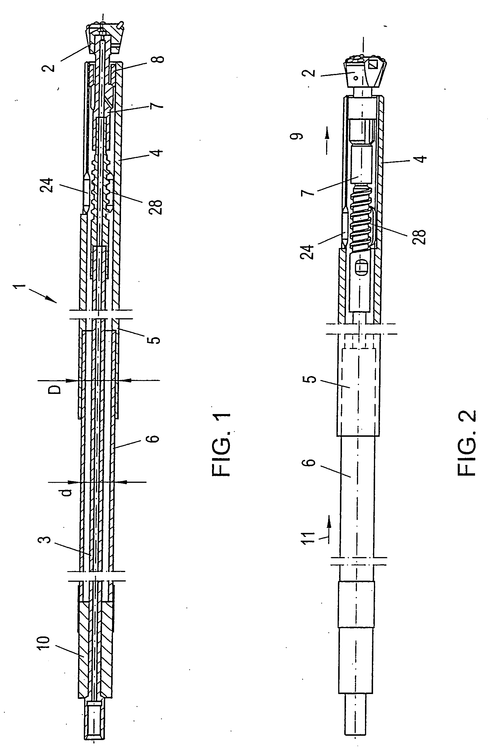
[0037] From the illustration according to FIGS. 1 and 2, it is apparent that a device for boring, or rotary percussion drilling, which is generally denoted by 1, comprises a drill bit schematically indicated by 2, which is configured for percussion or rotary percussion drilling via a drill rod assembly 3 to excavate material not illustrated in detail in FIGS. 1 and 2.

[0038] To the drill bit 2 is connected an envelope tube 4 having a comparably thick cross section and high strength, which envelope tube 4, on its end facing away from the drill bit 2, comprises a socket 5 in which a jacket tube 6 is received, said jacket tube 6 not only having a diameter d that is reduced relative to the diameter D of the envelope tube 4, but also a reduced wall thickness and strength.

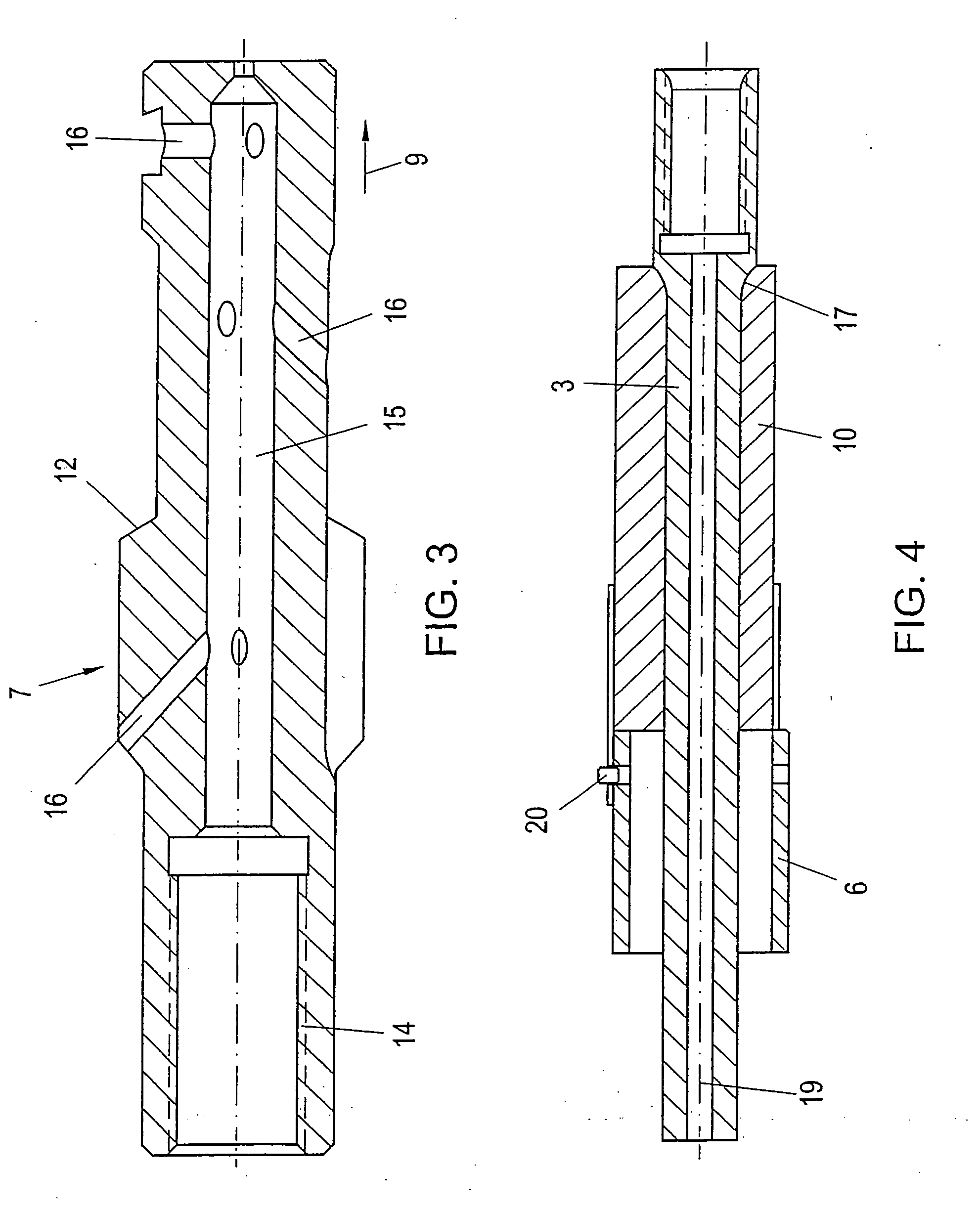
[0039] The drill bit 2 is directly coupled with the drill rod assembly 3 via an adapter 7 illustrated in detail in FIG. 3, via which adapter 7 also an entrainment and, in particular, tensile stress of the envelope tube ...


PUM


Abstract

In a method and device for boring or drilling, in particular percussion drilling or rotary percussion drilling, holes in soil or rock, wherein a borehole is formed by a percussive and/or rotary movement carried out by a drill bit (2) mounted on a drill rod assembly (3) and a jacket tube (6) coupled with the drill bit (2) is introduced into the borehole, it is provided that the jacket tube (6) is received in a socket (5) provided on the end facing away from the drill bit working surface, of an envelope tube (4) coupled with the drill bit (2), and that the jacket tube (6) is subjected to a percussive and/or compressive stress on its end facing away from the drill bit, whereby directionally precise boring or drilling is rendered feasible.

Description

[0001] This is a continuation of PCT / AT2004 / 000325 filed 28 Sep. 2004 and published in German.FIELD OF THE INVENTION [0002] The present invention relates to a method for boring or drilling, in particular percussion drilling or rotary percussion drilling, holes in soil or rock, wherein a borehole is formed by a percussive and / or rotary movement carried out by a drill bit mounted on a drill rod assembly and a jacket tube coupled with the drill bit is introduced into the borehole, as well as a device for boring or drilling, in particular percussion drilling or rotary percussion drilling, holes in soil or rock, wherein a borehole is formed by a percussive and / or rotary movement carried out by a drill bit mounted on a drill rod assembly and a jacket tube coupled with the drill bit is capable of being introduced into the borehole. PRIOR ART [0003] In the context of producing holes in soil or rock by, in particular, percussion drilling or rotary percussion drilling, various embodiments are...

Claims


Application Information

Patent Timeline
Patent Type & Authority Applications(United States)
IPC IPC(8): E21B4/00E21B17/07E21B7/20
CPCE21B7/201E21B7/20
Inventor MOCIVNIK, JOSEFEGGER-MOCIVNIK, RENE
Owner ALWAG TUNNELAUSBAU GMBH
Why Eureka
Try Eureka