Control device, non-transitory recording medium and image forming system
- Summary
- Abstract
- Description
- Claims
- Application Information
AI Technical Summary
Benefits of technology
Problems solved by technology
Method used
Image

Examples
first preferred embodiment
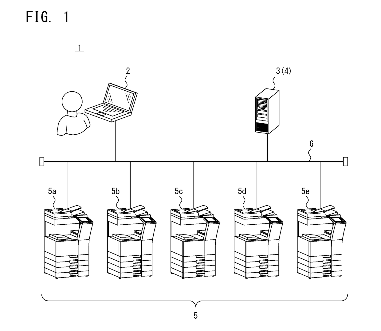
[0035]FIG. 1 is a diagram illustrating one configuration example of an image forming system 1 of the present invention. The image forming system 1 is configured so that an information processing device 2, a print server 3, a plurality of image forming apparatuses 5a, 5b, 5c, 5d, and 5c, can communicate with each other via a network 6 such as LAN (Local Area Network). FIG. 1 illustrates a case where the five image forming apparatuses 5a, 5b, 5c, 5d, and 5e are connected to the network 6, but a number of the image forming apparatuses 5 is not limited to five. Further, a number of the information processing device 2 is not limited to one, and thus the plurality of information processing devices 2 may be connected to the network 6. In the following description, when the plurality of image forming apparatuses 5a, 5b, 5c, 5d, and 5e is not discriminated from each other, they are generally described as the image forming apparatus 5.
[0036]The image forming apparatus 5 is an apparatus config...
second preferred embodiment
[0104]A second embodiment is described below. The first embodiment has illustrated the case where when the print server 3 transmits the print job 8 to the two or more image forming apparatuses 5 decided as spool destinations, the print server 3 transmits the print job 8 including image data for all pages to any image forming apparatus 5. However, when the print server 3 transmits the print job 8 including image data for all pages whose number is large to all the two or more image forming apparatuses 5 decided as spool destinations, a proportion of an entire storage capacity of the image forming system 1 occupied by one print job 8 becomes large. Therefore, the second embodiment describes an embodiment where a time until execution of a print job 8 is started in an image forming apparatus 5 used by a user is shortened, and simultaneously the proportion of an entire storage capacity of an image forming system 1 occupied by one print job 8 is reduced.
[0105]FIG. 12 is a diagram describin...
third preferred embodiment
[0117]A third embodiment is described below. This embodiment describes a technique, when a user logs in one image forming apparatus 5 to execute a print job 8 after the user issues the print job 8, can prevent the print job 8 from being improperly executed also in another image forming apparatus 5.
[0118]FIG. 15 is a diagram illustrating a concept of an operation of a plurality of image forming apparatuses 5a, 5b, and 5c according to the third embodiment. FIG. 15 illustrates a case where a print server 3 decides the three image forming apparatuses 5a, 5b, and 5c as spool destinations, and the print job 8 has been already spooled in the three image forming apparatuses 5a, 5b, and 5c. When the user logs in the image forming apparatus 5a and instructs the execution of the print job 8 in this state, the image forming apparatus 5a starts to execute the print job 8 (process P1). Accordingly, the image forming apparatus 5a transmits a job starting notification to the other image forming app...
PUM
 Abstract
Description
Claims
Application Information