Container energy storage system

a technology of energy storage and containers, applied in the field of containers, can solve the problems of water and foreign matter entering the interior of containers, damage to energy storage members and system controllers,

Active Publication Date: 2017-08-24
DELTA ELECTRONICS INC
View PDF20 Cites 11 Cited by
  • Summary
  • Abstract
  • Description
  • Claims
  • Application Information

AI Technical Summary

Problems solved by technology

Water and foreign matter may enter the interior of the container during transportation and damage the energy storage members and the system controller.

Method used


Image

  • Container energy storage system
  • Container energy storage system
  • Container energy storage system

Examples


Embodiment Construction

[0037]The making and using of the embodiments of the container energy storage system are discussed in detail below. It should be appreciated, however, that the embodiments provide many applicable inventive concepts that can be embodied in a wide variety of specific contexts. The specific embodiments discussed are merely illustrative of specific ways to make and use the embodiments, and do not limit the scope of the disclosure.

[0038]Unless defined otherwise, all technical and scientific terms used herein have the same meaning as commonly understood to one of ordinary skill in the art to which this invention belongs. It should be appreciated that each term, which is defined in a commonly used dictionary, should be interpreted as having a meaning conforming to the relative skills and the background or the context of the present disclosure, and should not be interpreted by an idealized or overly formal manner unless defined otherwise.

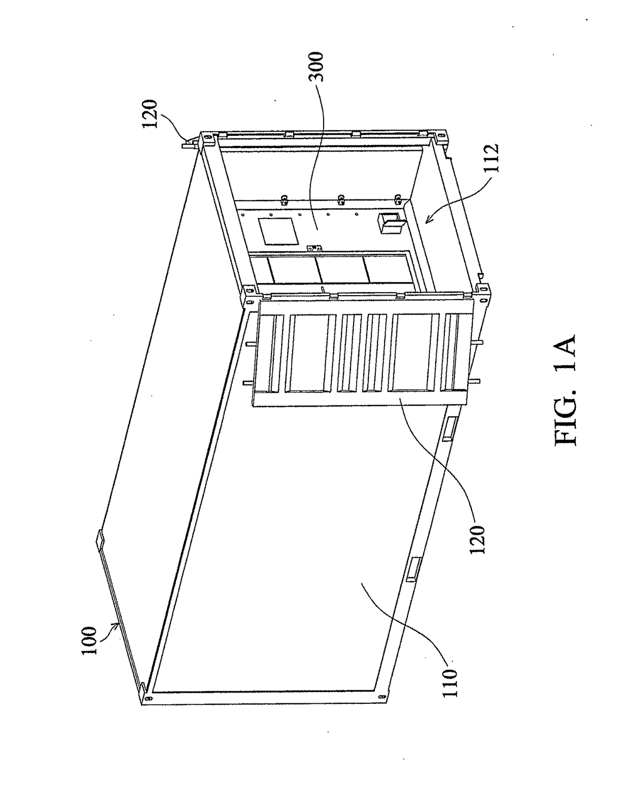
[0039]FIG. 1A is a schematic diagram of a container e...


PUM

PropertyMeasurementUnit
dimensionsaaaaaaaaaa
distanceaaaaaaaaaa
water resistanceaaaaaaaaaa

Abstract

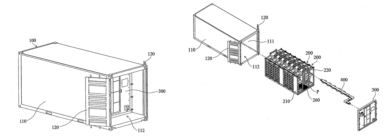
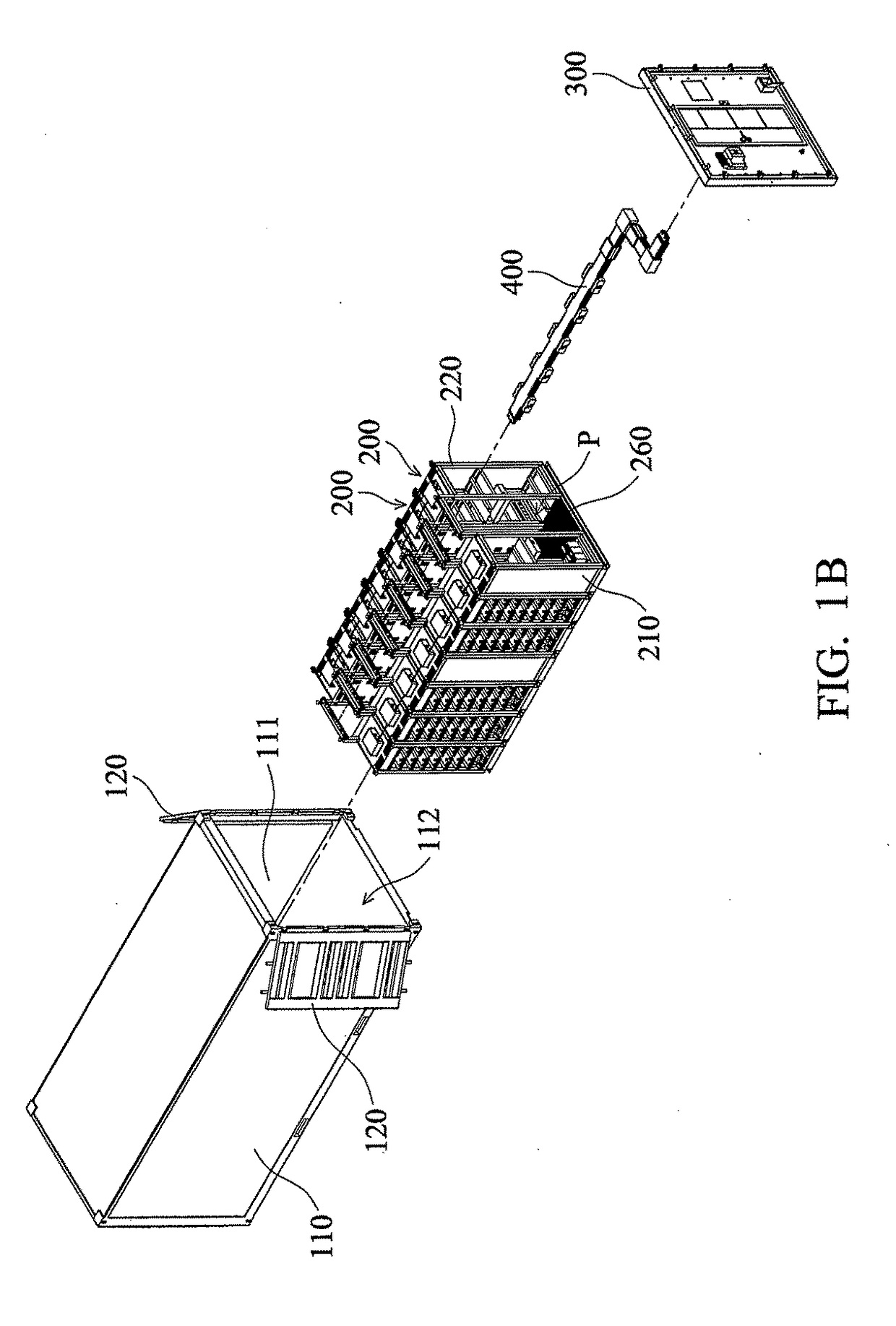
A container energy storage system is provided, including a container, a plurality of functional assemblies, and a splitting plate, wherein the splitting plate has a connecting port electrically connected to the functional assemblies. The container includes a hollow main body having an opening and two doors pivotally connected to the hollow main body. The functional assemblies are disposed in the hollow main body, and the splitting plate is disposed between the functional assemblies and the opening. When the doors are in a closed position, the doors cover the opening.

Description

CROSS REFERENCE TO RELATED APPLICATIONS[0001]The present application is based on, and claims priority from, Taiwan Patent Application No. 105105381, filed on Feb. 24, 2016, the disclosure of which is hereby incorporated by reference herein in its entirety.BACKGROUND OF THE INVENTION[0002]Field of the Invention[0003]The application relates in general to a container energy storage system, and in particular, to a container energy storage system having a splitting plate.[0004]Description of the Related Art[0005]Generally, a container energy storage system comprises a container, a plurality of energy storage members, and at least one system controller, wherein the energy storage members and the system controller are disposed in a container. Moreover, a passage is also provided in the container for moving, entering and leaving. The user can move to the aforementioned energy storage members or the system controller along the passage to operate, maintain or replace.[0006]However, in order t...

Claims


Application Information

Patent Timeline
Patent Type & Authority Applications(United States)
IPC IPC(8): H02B1/34H02B1/30H02B1/20H02B1/28H01M50/204H01M50/271
CPCH02B1/34H02B1/28H02B1/306H02B1/20H02B1/30H05K7/1432H01M2220/10E04H5/04Y02E60/10H01M50/204H01M50/271A47B53/00B65D90/0073H05K7/1497B65D90/0046B65D90/0053E04H5/00
Inventor CHEN, CHIN-MINGLIN, MU-MIN
Owner DELTA ELECTRONICS INC
Why Eureka
Try Eureka