System and method for conveyor rack and elevator

a conveyor rack and elevator technology, applied in the field of casting stone production, can solve the problems of high labor intensity, complex multi-faced shapes, and high cost of production of complex multi-faced shapes,

Active Publication Date: 2017-08-31
WEICK STEVEN HOWARD
View PDF2 Cites 10 Cited by
  • Summary
  • Abstract
  • Description
  • Claims
  • Application Information

AI Technical Summary

Problems solved by technology

However, the vibrant dry tamp method generally requires one flat, unexposed side to the stone design, thereby making complex multi-faced shapes, such as an “L” shape and similar shapes more costly to produce.
However, these processes for manufacturing cast stone are costly and labor intensive.

Method used


Image

  • System and method for conveyor rack and elevator
  • System and method for conveyor rack and elevator
  • System and method for conveyor rack and elevator

Examples


Embodiment Construction

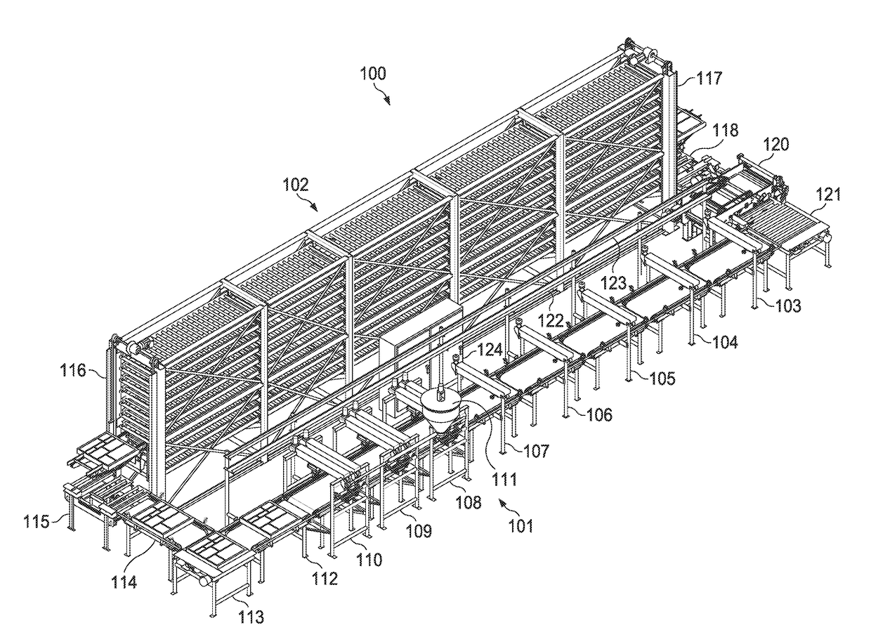
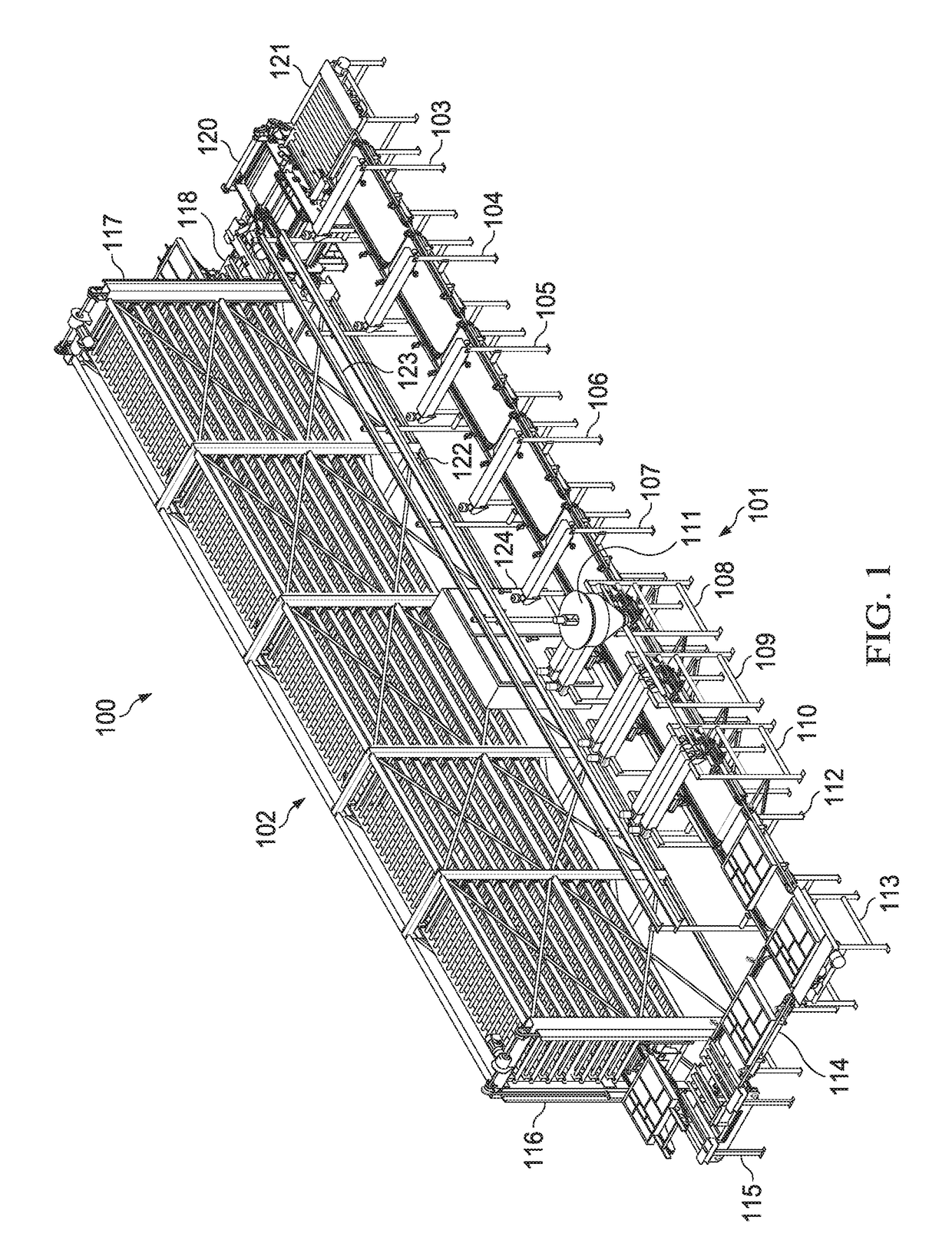
[0056]Referring to FIG. 1, system 100 includes a set of conveyor stations 101 connected to a drying rack 102. Set of conveyor stations 101 includes spray stations 103, 104, 105, 106, and 107. Spray station 104 is connected to spray station 103, spray station 105 is connected the space station 104, spray station 106 is connected to spray station 105, and spray station 107 is connected to spray station 106. Fill station 108 is connected to spray station 107. Fill station 109 is connected to fill station 108. Fill station 110 is connected to fill station 109. Hopper 111 is connected to each of fill stations 108, 109, and 110. Vibration table 112 is connected to fill station 110. Right angle transition (“RAT”) table 113 is connected to vibration table 112. Conveyor table 114 is connected to RAT table 113. Elevator entry table 115 is connected to vibration table 114 and entry elevator 116 of drying rack 102. Elevator 117 of drying rack 102 is connected to exit table 118. Demolder 120 is ...


PUM

PropertyMeasurementUnit
compressive strengthaaaaaaaaaa
time periodaaaaaaaaaa
lengthaaaaaaaaaa

Abstract

A system and method for manufacturing a set of cast stones includes a set of spray stations, a set of fill stations, a set of vibration tables, a drying rack, and a demolder connected to the drying rack. A controller is connected to each of the set of spray stations, the set of fill stations, the set of vibration tables, the drying rack, and the demolder, each of which has a set of sensors connected to the controller. The set of spray stations include a set of release stations and a set of color stations. A mold is sprayed with a release product, a set of colors, and then filled with a cementitious material. Once vibrated, the cementitious material is dried to form the set of cast stones, which is then automatically released from the mold utilizing the demolder.

Description

CROSS-REFERENCE TO RELATED APPLICATION[0001]This application claims priority to U.S. Provisional Application No. 62 / 295,221, filed Feb. 15, 2016. This patent application is incorporated by reference herein in its entirety to provide continuity of disclosure.FIELD OF THE INVENTION[0002]The disclosed embodiments generally relate to creating cast stone. More particularly, the disclosed embodiments relate to a system and method for creating cast stone using reusable molds that works autonomously.BACKGROUND OF THE INVENTION[0003]Cast stone is a product that simulates natural cut stone used as an architectural feature, trim, ornament, or facing of buildings, walls, or other structures. Cast stone is made from a cementitious material, such as concrete, that includes fine and course aggregates, Portland cement, water, coloring, and optional chemical admixtures. Two methods to manufacture cast stone are the vibrant dry tamp method and the wet cast method.[0004]Each method requires design mix...

Claims


Application Information

Patent Timeline
Patent Type & Authority Applications(United States)
IPC IPC(8): B28B17/00B28B5/02B28B1/14B28B7/38B28B11/24B28B13/06B28B7/06
CPCB28B17/0081B28B13/062B28B5/022B28B1/14B28B7/38B28B11/243B28B17/0072B28B7/06B28B5/04B28B15/00
Inventor WEICK, STEVEN HOWARDSTREMPKE, JUSTIN D.CAGLE, JAYTON T.POWLEDGE, TROYSMITH, WILLIAM STEVEN
Owner WEICK STEVEN HOWARD
Why Eureka
Try Eureka