
Conveyor belt connector and method for forming a belt

a technology of conveyor belts and connectors, which is applied in the direction of belts, belt fastenings, driving belts, etc., can solve the problems of affecting the service life of conveyor belts

Active Publication Date: 2017-08-31
FENNER PLC
View PDF1 Cites 0 Cited by
  • Summary
  • Abstract
  • Description
  • Claims
  • Application Information

AI Technical Summary

Benefits of technology

The present invention provides an improved belt connector and a belt with an improved connector. The belt connector has two connectors that are pivotable relative to each other and a connecting link that connects the two connectors. The connecting link is made up of a first connector and a second connector that can pivot about a first and second axis, respectively. The method of connecting the belt material involves inserting the connectors into the ends of the belt material and then rotating the connectors to bring the ends together. This creates a continuous loop of belt material. The technical effects of the invention include improved durability, reliability, and flexibility of the belt connector, as well as a simpler and more efficient method of creating an endless belt loop.

Problems solved by technology

However, it can take a substantial amount of time to prepare and weld a belt.
In addition, after a belt is welded, there is a waiting time before the belt should be fully tensioned.
Therefore, the welding process can create undue down time for machinery.
However, such fasteners significantly limit the amount of tension that can be applied to the belt.
Such fasteners also tend to creep during use, which frequently causes the connector to become detached.

Method used


Image

  • Conveyor belt connector and method for forming a belt
  • Conveyor belt connector and method for forming a belt
  • Conveyor belt connector and method for forming a belt

Examples


Embodiment Construction

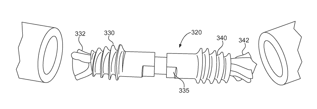
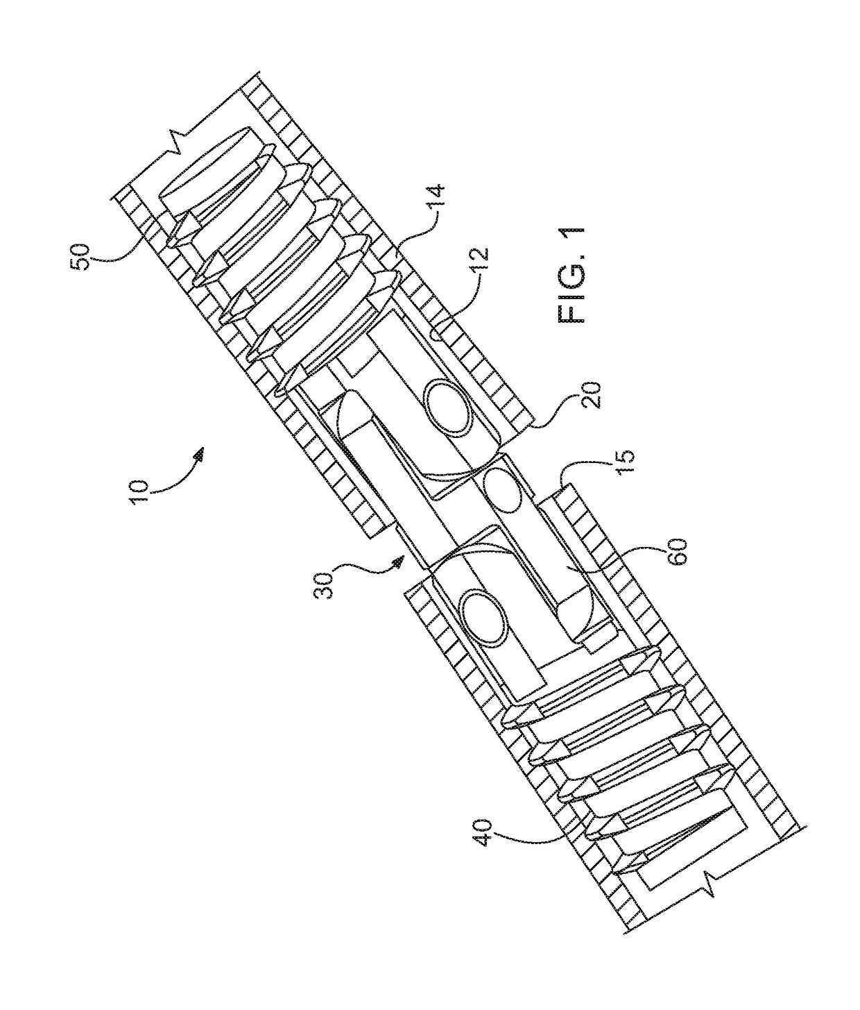
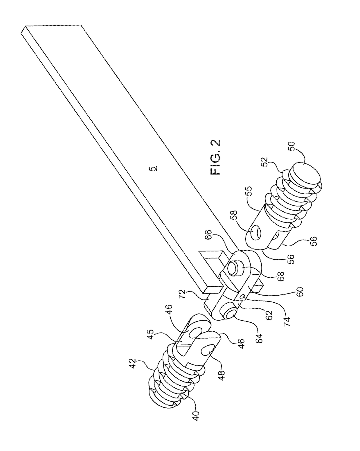
[0017]Referring now to the figures, wherein like elements are numbered alike throughout, an endless belt is designated 10. The belt 10 is formed of a length of belt material having two ends connected by a belt connector 30. The belt connector 30 connects the ends of the belt to form a continuous loop. The belt is configured to be entrained around a plurality of rotatable elements, such as rollers or pulleys. For instance, in the present instance, the belt is entrained around a plurality of pulleys or sheaves, and each pulley has a rotatable groove in which the belt rides.

[0018]The belt 10 may be formed of any of a variety of materials. For instance, the belt 10 is formed from an elongated length of belting material which may be any of a variety of materials, including elastomers, such as rubber, silicon or any of a variety of plastics, such as polyurethane. In the present instance, the belting material is a length of extruded polyurethane having a hardness of about 85 or 89 duromete...


PUM

PropertyMeasurementUnit
thread angleaaaaaaaaaa
thicknessaaaaaaaaaa

Abstract

A belt and belt connector is provided for forming a continuous belt loop. The belt connector includes a first element insertable into a first end of the belt and a second element insertable into a second end of the belt. The first element may include exterior threads for positively engaging the interior of the belt. Additionally, the belt connector may include a connecting link that connects the first and second elements so that the first and second elements are pivotable relative to one another. Additionally, the connecting link may be configured to that the first element is pivotable relative to the connecting link about a first pivot axis and the connecting link may be pivotable relative to the second element about a second pivot axis that is transverse the first pivot axis.

Description

PRIORITY CLAIM[0001]This application claims priority to U.S. Provisional appl. No. 62 / 301,263 filed Feb. 29, 2016. The entire disclosure of the foregoing application is hereby incorporated herein by reference.FIELD OF THE INVENTION[0002]This present invention relates to endless belts, such as conveyor belts. More specifically, the invention relates to connectors for endless belts.BACKGROUND OF THE INVENTION[0003]Continuous belts made of thermoplastic material, such as polyurethane, are used in a variety of conveyor applications. A common method for forming such belts is to heat fuse or weld the ends of a length of belting in order to form a continuous loop. However, it can take a substantial amount of time to prepare and weld a belt. In addition, after a belt is welded, there is a waiting time before the belt should be fully tensioned. Therefore, the welding process can create undue down time for machinery. To reduce down-time, a mechanical fastener may be used to connect the ends o...

Claims


Application Information

Patent Timeline
Patent Type & Authority Applications(United States)
IPC IPC(8): B65G15/32F16G3/08
CPCF16G3/08B65G15/32F16G1/14F16G3/00B65G17/00
Inventor RAMACHANDRA, SUNILHESTON, STEPHEN F.PURSEL, BRIAN M.
Owner FENNER PLC
Learn More