
Quick-connect clip-on connector

a clip-on connector and quick-connect technology, applied in the direction of couplings, mechanical equipment, etc., can solve the problems of insufficient force on the flange of the end fitting, insufficient retention of the jaws, and relatively fragile use of the single lozenge-shaped latch part, so as to improve the resistance of the jaws to pulling out, improve the connector, and increase the resistance of the jaws

Active Publication Date: 2018-10-09
NOBEL PLASTIQUES
View PDF12 Cites 2 Cited by
  • Summary
  • Abstract
  • Description
  • Claims
  • Application Information

AI Technical Summary

Benefits of technology

The invention improves a connector by making it stronger and more resistant to pulling out. This is achieved by increasing the force exerted by the jaws and making it difficult to remove the end fitting. The design is simple and easy to assemble. Two O-rings are used, separated by a spacer ring, and a closure ring is force-fitted to immobilize the O-rings and spacer ring. The closure ring has raised patterns that facilitate force-fitting.

Problems solved by technology

The single lozenge-shaped latch part proves relatively fragile in use.
To enable its elastic operation, it is necessary to provide connecting parts that are not too thick or too rigid and because of this the jaws may be retained insufficiently and not exert sufficient force on the flange of an end fitting to prevent pulling out of the end fitting.

Method used


Image

  • Quick-connect clip-on connector
  • Quick-connect clip-on connector
  • Quick-connect clip-on connector

Examples


Embodiment Construction

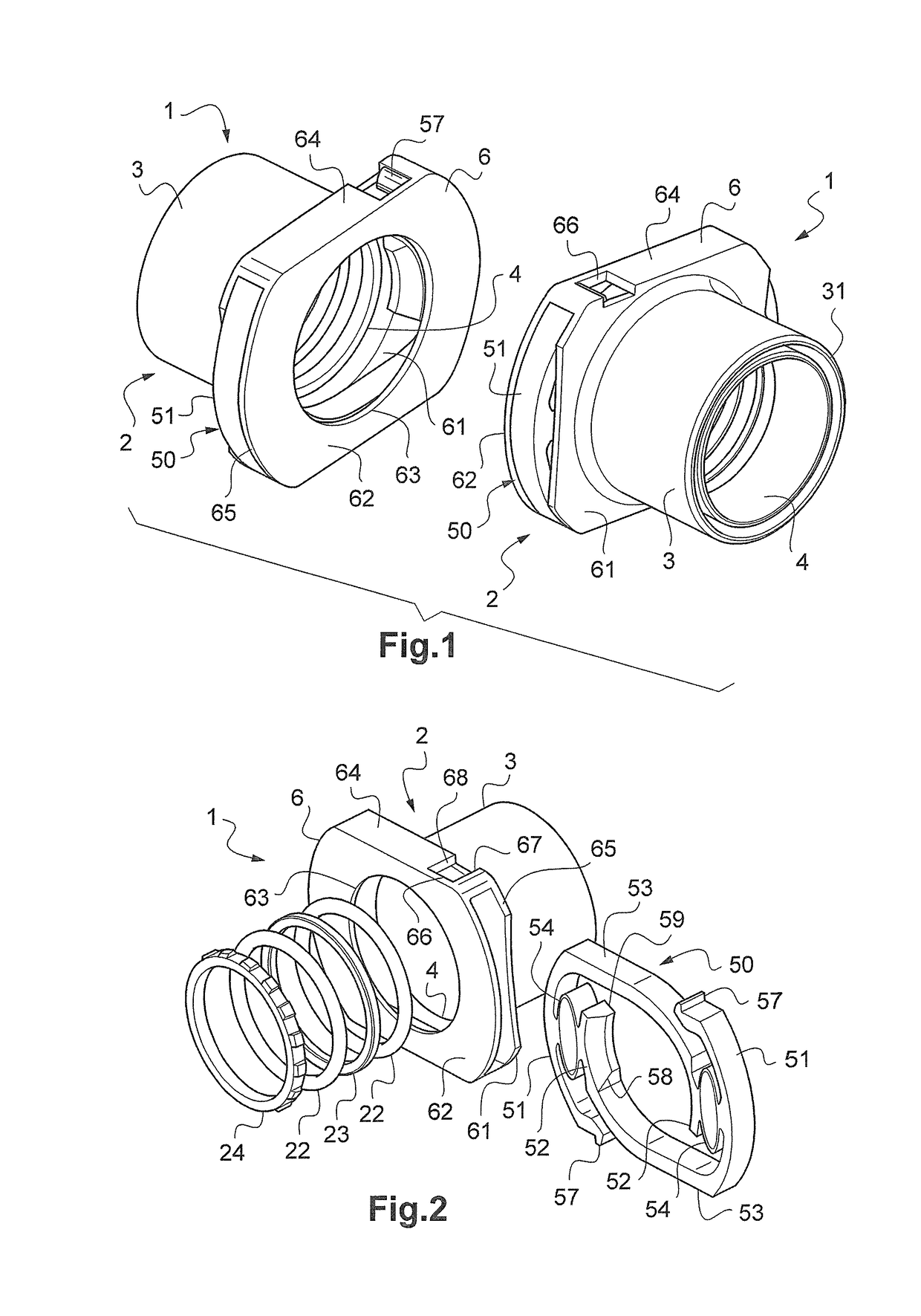
[0022]The quick-connect connector 1 essentially comprises a body 2 that includes at the rear a tubular part in the form of a hollow spigot 3 and at the front a cylindrical cavity or chamber 4 in which is engaged a male end fitting 20 formed of a bush 26 provided with a clip-on flange 25. The spigot 3 includes an axial circular groove 31 for the axial insertion of a pipe 40. Alternatively, the spigot 3 may include on its exterior surface connecting profiles that are not represented, for example barbs or single or double beads, for force-fitting into a pipe, or may be fastened to a tube or some other member by welding (rotation, ultrasound, induction or laser welding).

[0023]As FIG. 3 shows, the cylindrical cavity 4 defines an interior cylindrical space having a cylindrical first section starting from the opening of the cylindrical cavity 4 at the front of the body 2 and extending as far as an internal cylindrical housing 5, defining a cylindrical passage having an inside diameter suit...


PUM


Abstract

This female clip-onconnector (1), which is adapted to cooperate with a male attachment end fitting (20) of the type with a central bush (26) and a flange (25), includes a body (2) forming a cylindrical cavity and a transverse latch housing in front of the opening of the cylindrical cavity forming a housing for a single latch part (50) including two actuating parts (51) connected respectively to two jaws (52), said actuating parts and said jaws acting in a same direction transverse to the axis of the body, and spring means (54) for spring-loading each jaw (52) at all times towards its rest position in which the jaw (52) is close to the axis and in which the actuating part (51) is in its radially outermost position.

Description

CROSS REFERENCE TO RELATED APPLICATIONS[0001]The present application is a 35 U.S.C. § 371 National Phase conversion of PCT / EP2013 / 070646, filed Oct. 3, 2013, the disclosure of which is incorporated herein by reference.TECHNICAL FIELD OF THE INVENTION[0002]The present invention concerns a female clip-on connector adapted to cooperate with a flanged male attachment end fitting.BACKGROUND OF THE INVENTION[0003]In the present document, this assembly of two male-female elements is called a “connector”. It is normal, notably in the automotive industry, to use such clip-on connectors to produce the quick and demountable connection of an element of a fluid (for example fuel, oil or water) circuit to another circuit element. Virtually standardized in the industry is the use of male end fittings including a cylindrical bush surrounded by a flange and the female connectors include a cylindrical cavity adapted to receive at least the end of the bush and an elastic latch adapted to lock onto the...

Claims


Application Information

Patent Timeline
Patent Type & Authority Patents(United States)
IPC IPC(8): F16L37/00F16L37/084
CPCF16L37/0841
Inventor CHINTALAPATI, RAMAKRISHNAM RAJUPORIGNAUX, FABIEN
Owner NOBEL PLASTIQUES
Learn More