
Controlled discharge connector lead

a technology of discharge connector and discharge connector, which is applied in the manufacture of contact parts, coupling device details, coupling device connections, etc., can solve the problems of rapid discharge and damage to components, invisible damage to electronic components through esd, and damage to components

Inactive Publication Date: 2013-05-09
PIVOT CASTLE LLC
View PDF5 Cites 1 Cited by
  • Summary
  • Abstract
  • Description
  • Claims
  • Application Information

AI Technical Summary

Benefits of technology

The patent describes a connector lead with a resistive member that helps to dissipate charge during connection and provides a conductive path around the resistive member. The lead can be used in various electrical components such as capacitors, integrated circuits, memory chips, and batteries. The patent also provides an improved mating connector and insulating guides to help align the connectors. The technical effects of the invention include improved current dissipation, reliable connection, and better performance of the connected components.

Problems solved by technology

Invisible damage may be done through ESD to some electronic components, such as capacitors, transistors, etc., that are an integral part of integrated circuit components and circuit board components in modern electronic devices.
Two leads that come in contact during a hot-swap may result in rapid discharge and potential damage to components coupled to the leads.

Method used


Image

  • Controlled discharge connector lead
  • Controlled discharge connector lead
  • Controlled discharge connector lead

Examples


Embodiment Construction

[0036]The subject matter of the present invention is described with specificity herein to meet statutory requirements. However, the description itself is not intended to limit the scope of this patent. Rather, the inventors have contemplated that the claimed subject matter might also be embodied in other ways, to include different steps or combinations of steps similar to the ones described in this document, in conjunction with other present or future technologies. Moreover, although the terms “step” and / or “block” may be used herein to connote different elements of methods employed, the terms should not be interpreted as implying any particular order among or between various steps herein disclosed unless and except when the order of individual steps is explicitly described.

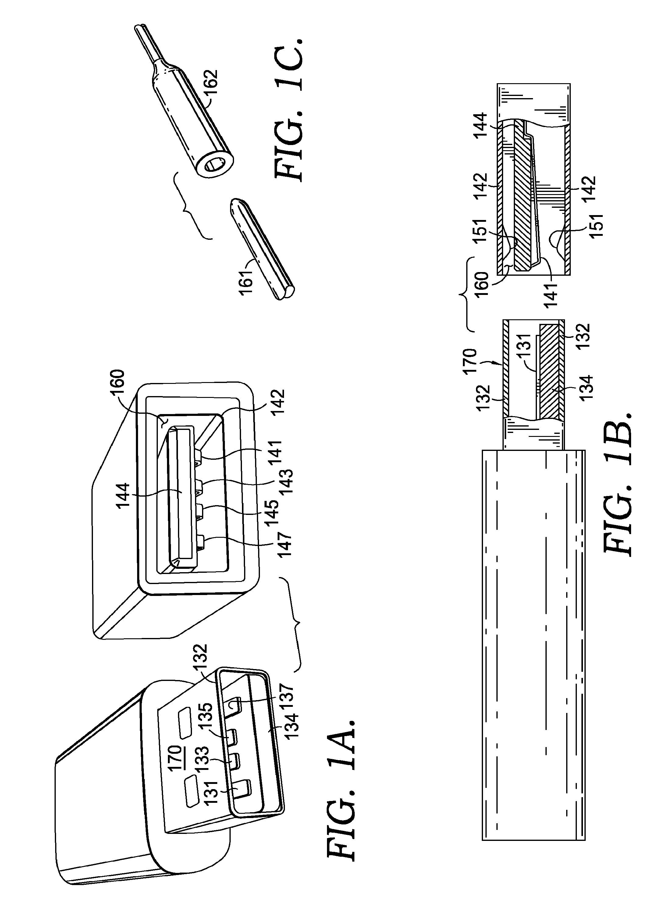
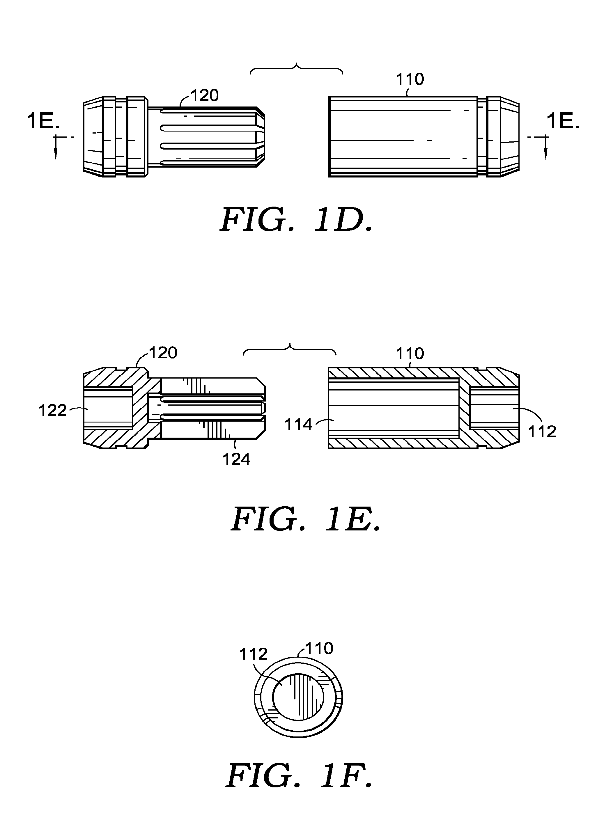
[0037]Turning now to FIGS. 1A-1F, there are depicted therein a number of views of different connector leads that may encounter unwanted, damaging rapid charge or discharge upon connection. Leads of such connector...


PUM

PropertyMeasurementUnit
diameteraaaaaaaaaa
diameteraaaaaaaaaa
diameteraaaaaaaaaa

Abstract

When a hobby enthusiast has recharged the battery for a remote controlled vehicle, such as a scale facsimile automobile, boat, helicopter or airplane, the battery must be connected again to the vehicle drive system, to provide power. This operation is typically performed by connecting each lead of an electronic speed controller to each corresponding lead of the battery, through a removable barrel receptacle lead and a mating barrel plug lead respectively, attached to each corresponding lead. An improved connector lead is described herein that protects components that may be attached to either lead in a connection. The charge dissipates in a resistive member that is physically coupled to a conductive member to form at least in part a first lead. When an improved lead is connected to a mating lead, the connection initially provides a charge dissipation path through the resistive member, but subsequently provides a bypass, current carrying conductive path around the resistive member from one component to another. By making use of an improved connector, electrical components are protected, not only from hot-swap current, but also from electrostatic discharge in general.

Description

CROSS-REFERENCE TO RELATED APPLICATIONS[0001]This application is a divisional of application Ser. No. 12 / 874,867, filed Sep. 2, 2010, entitled CONTROLLED DISCHARGE CONNECTOR LEAD. Application Ser. No. 12 / 874,867 is hereby incorporated by reference in its entirety.BACKGROUND OF THE INVENTION[0002]Electrical connectors are a vital, but an often overlooked part of our modern technological world. Connector design typically addresses mechanical requirements: being easy to use, durable, reliable, and safe. Connector design also typically is adapted to the electrical requirements of the application, e.g., having leads that are sized appropriately for the current that the connector will carry.[0003]Electrostatic discharge (ESD) is one concern of electrical connector design. Invisible damage may be done through ESD to some electronic components, such as capacitors, transistors, etc., that are an integral part of integrated circuit components and circuit board components in modern electronic ...

Claims


Application Information

Patent Timeline
Patent Type & Authority Applications(United States)
IPC IPC(8): H01R43/00H01R43/20H01R43/26
CPCH01R13/187H01R13/53H01R13/6616Y10T29/49208H01R43/20H01R43/26Y10T29/49117H01R43/00H01R43/16
Inventor HOFER, RICHARD A.DEL CASTILLO, PATRICK D.
Owner PIVOT CASTLE LLC
Learn More