Rotor bearing temperature sensor

a temperature sensor and rotating bearing technology, applied in the direction of bearings, rotary bearings, bearing components, etc., can solve the problems of machine failure, overheating damage to components,

Active Publication Date: 2017-08-31
SAFRAN ELECTRICAL & POWER UK LTD
View PDF1 Cites 0 Cited by
  • Summary
  • Abstract
  • Description
  • Claims
  • Application Information

AI Technical Summary

Benefits of technology

[0007]The assembly of the present invention permits more accurate monitoring of a temperature of a race of a bearing, especially in cooled environments, which are cooled by fluids such as air, water or oil, where heat generated in a race of a bearing may be relatively quickly dissipated to surrounding components or to the surrounding environment, or to coolants where they are present. Such dissipation can happen quickly enough that it is not detected by a sensor, but slowly enough that damage is caused to components which overheat. High temperature gradients can therefore be present in the region of a bearing and so mounting a temperature sensor at or in close proximity to a race of bearing can be advantageous. The arrangement of the invention includes a thermal isolator which generally isolates or insulates the sensor assembly from heat exchange with the surrounding environment and so reduces the effect on the sensor readings of either heating or cooling in the surrounding environment or surrounding components and can also therefore be a thermal insulator. Traditionally, sensors mounted to the bearing structure, or directly to the bearing itself, suffer from a heat sink effect of surrounding structures and components and so do not accurately detect temperature rise with a sufficiently timely response before bearing failure, which can result in a machine failure.
[0031]The temperature sensor may be mounted in or adjacent a cooled wall of the cooled chamber. This makes the thermal insulator of the present invention particularly advantageous for insulating the temperature sensor from the cooling effect of the cooled wall.

Problems solved by technology

Such dissipation can happen quickly enough that it is not detected by a sensor, but slowly enough that damage is caused to components which overheat.
Traditionally, sensors mounted to the bearing structure, or directly to the bearing itself, suffer from a heat sink effect of surrounding structures and components and so do not accurately detect temperature rise with a sufficiently timely response before bearing failure, which can result in a machine failure.

Method used


Image

  • Rotor bearing temperature sensor
  • Rotor bearing temperature sensor
  • Rotor bearing temperature sensor

Examples


Embodiment Construction

)

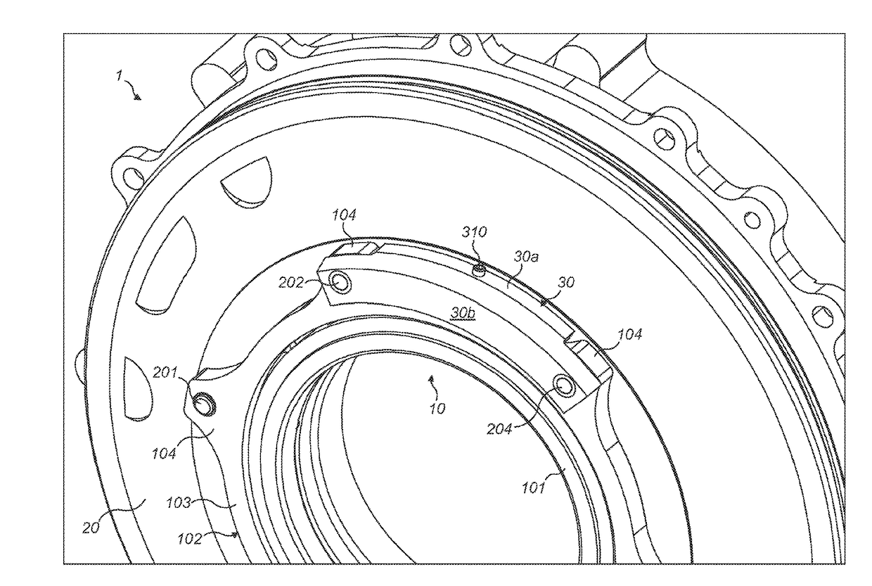
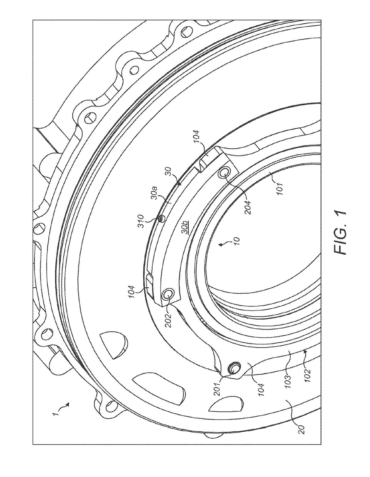
[0039]FIG. 1 shows a bearing of assembly 1 of the present invention. In the illustrated embodiment, the bearing assembly of the invention is provided in a generator. The problems herein will be described with respect to such a generator, in particular an air or oil cooled generator, but the heating and temperature monitoring problems addressed by the invention apply equally to many other types of machines, as will become apparent on reading the following description.

[0040]The illustrated assembly comprises a bearing 10. The bearing 10 comprises an inner race 101 and an outer race 102. In the illustrated embodiment, the bearing 10 is mounted in a structure, which takes the form of a wall section 20. In the embodiment described, wall section 20 divides a chamber which contains a main stator (not shown) of a generator from a further chamber which is hermetically sealed and divided from the chamber containing the stator. The chamber containing the stator, in which the temperature senso...


PUM


Abstract

A bearing assembly is provided with an improved mounting for a temperature sensor for monitoring a temperature of a race of the bearing. The assembly includes a temperature sensor assembly mounted to the race of the bearing and a thermal insulator arranged to thermally insulate the sensor from heat exchange with the surrounding environment and / or neighbouring components to which the bearing or assembly is mounted, in order to improve accuracy, reliability and speed of response of the temperature sensor readings.

Description

FIELD OF THE INVENTION[0001]The present invention relates to a mounting arrangement for a temperature sensor. In particular, the invention relates to a mounting arrangement for mounting a sensor for detecting a temperature in a bearing, preferably a roller bearing or a ball bearing.BACKGROUND OF THE INVENTION[0002]Modern machinery has long included rotating components, which are generally supported by bearings, to journal the rotating part in a body, chassis, frame or other structural element of the machinery. Bearings in rotation generate heat due to friction. The amount of heat generated will vary depending upon the state of lubrication of the bearing, the magnitude of lateral loads being transmitted through the bearing and its speed of rotation, among other factors.[0003]Overheating in bearings can be a problem, since it can result in distortion and / or heat damage to components of the bearing. Additionally, such overheating can cause distortion, fatigue and heat damage to surroun...

Claims


Application Information

Patent Timeline
Patent Type & Authority Applications(United States)
IPC IPC(8): F16C19/52F16C33/58
CPCF16C33/586F16C19/525
Inventor HOWARD, DARREN
Owner SAFRAN ELECTRICAL & POWER UK LTD
Why Eureka
Try Eureka